Control method and system, server and terminal
A control method and server technology, applied in the field of information processing, can solve problems such as inability to adapt to spatial shapes, inability to purify air, and unfavorable user experience
- Summary
- Abstract
- Description
- Claims
- Application Information
AI Technical Summary
Problems solved by technology
Method used
Image

Examples
Embodiment 1
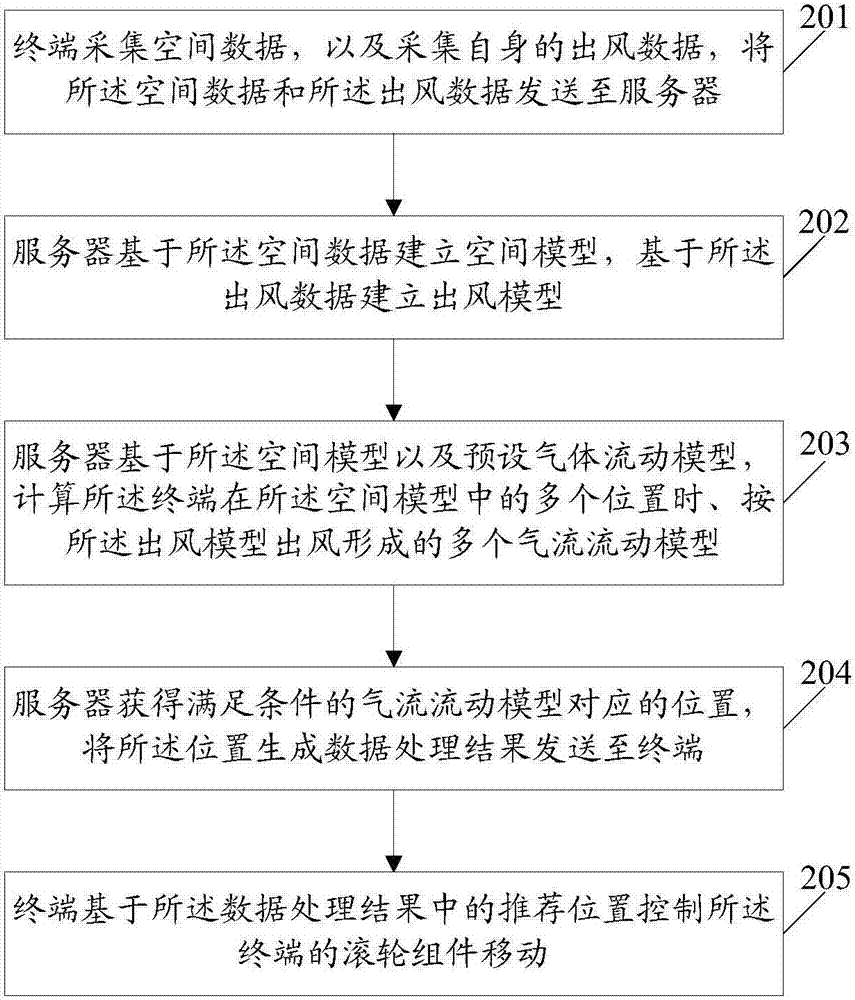
[0061] An embodiment of the present invention provides a control method. figure 2 It is a schematic flow chart of the control method in Embodiment 1 of the present invention; figure 2 As shown, the method includes:
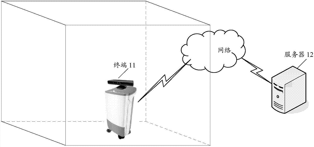
[0062] Step 201: The terminal collects spatial data and its own wind data, and sends the spatial data and the wind data to a server.
[0063] In this embodiment, the terminal has an air purification function, that is, it can inhale external air and send out purified clean air through the internal purification function; based on this, the terminal has at least an air inlet and an air outlet. As an illustration, the terminal may be an air purifier in practical applications.
[0064] Here, the spatial data is the spatial data in the spatial region where the terminal is located. Taking the ground where the terminal is located as the bottom surface as an example, the spatial data may include: spatial height, spatial length and width, etc.; here, The space refers t...
Embodiment 2
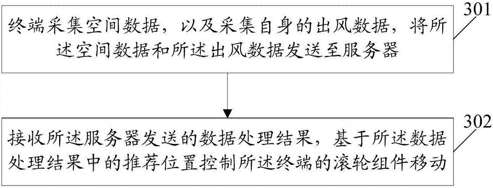
[0086] The embodiment of the present invention also provides a control method, which is applied to a terminal. image 3 It is a schematic flow chart of the control method of Embodiment 2 of the present invention; as image 3 As shown, the method includes:
[0087] Step 301: The terminal collects spatial data and its own wind data, and sends the spatial data and the wind data to a server.
[0088] In this embodiment, the terminal has an air purification function, that is, it can inhale external air and send out purified clean air through the internal purification function; based on this, the terminal has at least an air inlet and an air outlet. As an illustration, the terminal may be an air purifier in practical applications.
[0089] Here, the spatial data is the spatial data in the spatial region where the terminal is located. Taking the ground where the terminal is located as the bottom surface as an example, the spatial data may include: spatial height, spatial length and...
Embodiment 3
[0095] The embodiment of the present invention also provides a control method, which is applied to a server. Figure 4 It is a schematic flow chart of the control method of the third embodiment of the present invention; as Figure 4 As shown, the method includes:
[0096] Step 401: The server obtains the spatial data and wind data sent by the terminal, establishes a spatial model based on the spatial data, and establishes a wind model based on the wind data.
[0097] Here, on the one hand, the server establishes a spatial model based on the spatial data sent by the terminal; specifically, the server may establish a three-dimensional spatial model of the space where the terminal is located based on the image data and distance data sent by the terminal; The three-dimensional space model can reflect the space area where the terminal is located. On the other hand, the server establishes an air outlet model of clean air based on the air outlet data sent by the terminal, including...
PUM
 Abstract
Description
Claims
Application Information