
Guiding structure for use with scanner that prevent deformation of scanned images, and scanner

A guiding structure and scanner technology, applied in the direction of image communication, electrical components, etc., can solve the problems of large force changes, scanning image shaking and deformation, and easy speed and speed, so as to avoid shaking and deformation and improve scanning quality effect

Active Publication Date: 2017-12-15
AVISION
View PDF5 Cites 0 Cited by
  • Summary
  • Abstract
  • Description
  • Claims
  • Application Information

AI Technical Summary

Problems solved by technology

In this way, due to the large change of force on the object to be scanned in the paper feeding channel (instantaneous generation and release of resistance between the object to be scanned and the roller group), the speed of travel is easy to fluctuate, so it is easy to cause vibration and deformation of the scanned image. like Figure 9 shown

Method used


Image

  • Guiding structure for use with scanner that prevent deformation of scanned images, and scanner
  • Guiding structure for use with scanner that prevent deformation of scanned images, and scanner
  • Guiding structure for use with scanner that prevent deformation of scanned images, and scanner

Examples


Embodiment Construction

[0053] The directional terms mentioned in the following embodiments, such as: up, down, left, right, front or back, etc., are only referring to the directions of the drawings. Accordingly, the directional terms used are illustrative and not limiting of the invention.

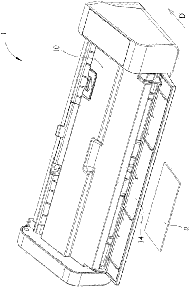
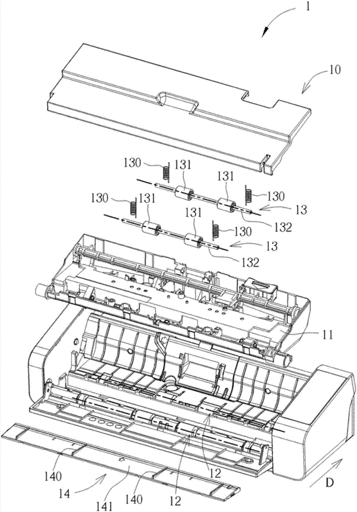
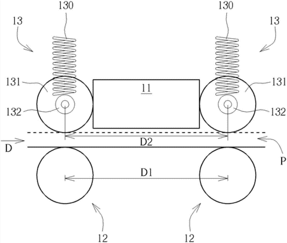
[0054] see Figure 1 to Figure 3 , figure 1 It is a schematic diagram of the appearance of the scanner 1 according to the embodiment of the present invention, figure 2 It is an exploded view of some internal components of the scanner 1 according to the embodiment of the present invention, image 3 It is a schematic diagram of a part of the internal structure of the scanner 1 according to the embodiment of the present invention. Such as Figure 1 to Figure 3As shown, the scanner 1 includes a housing 10 , an image capture module 11 , two driving roller sets 12 , two idler wheel sets 13 and a guiding structure 14 . The image capture module 11 is disposed in the casing 10 and used for capturing the image of t...


PUM


Abstract

A scanner includes an image capturing module, a driving roller set, an idler set and a guiding structure. The image capturing module captures the image of the object to be scanned, the driving roller set drives the object to be scanned to move in the paper feeding direction and the idler set presses the object to be scanned elastically to prevent the object to be scanned from moving in the direction offsetting from the paper feeding direction. A paper feeding passage is formed between the driving roller set and the idler set, and the guiding structure is disposed in front of the paper feeding passage and used for guiding a normal direction of a front edge of the object to be scanned to be at a skew angle substantially not equal to 0 degree with respect to the paper feeding direction. Therefore, the present invention can effectively reduce the variation of the bearing force of the object to be scanned when traveling in the paper feeding passage, thereby preventing the scanned image from being deformed.

Description

technical field [0001] The invention relates to a guiding structure for a scanner and the scanner, in particular to a guiding structure and the scanner for preventing deformation of scanned images. Background technique [0002] In order to meet the needs of users, most of the currently commercially available scanners can support paper and cards of different thicknesses. Since the thickness of the card generally falls between 0.8 and 1.25 mm, and the thickness of the paper is about 0.1 mm, the difference is quite large, so the idler of the scanner is usually provided with an elastic member, so that the idler can cooperate with the object to be scanned to compress The elastic member moves up and down relative to the driving wheel, so that the height of the paper feeding channel between the idle wheel and the driving wheel can be adjusted according to the thickness of the object to be scanned. [0003] However, in this design, if the object to be scanned is thicker, the deform...

Claims


Application Information

Patent Timeline
Patent Type & Authority Applications(China)
IPC IPC(8): H04N1/00H04N1/04
CPCH04N1/00519H04N1/00599H04N1/04H04N1/1215H04N1/123
Inventor 施盛耀童永宏
Owner AVISION
Learn More