Flexible auxiliary tool

An auxiliary tooling and flexible technology, applied in the direction of feeding device, manufacturing tool, positioning device, etc., can solve the problems of large drop, deformation of stamping parts, etc., achieve the effect of strong versatility and avoid vibration deformation

Inactive Publication Date: 2020-03-27
CHERY AUTOMOBILE CO LTD
View PDF9 Cites 0 Cited by
  • Summary
  • Abstract
  • Description
  • Claims
  • Application Information

AI Technical Summary

Problems solved by technology

[0003] The purpose of this invention is to propose a flexible auxiliary tooling, which can solve the problem of deformation of stamping parts with large drop at the end of the production line

Method used


Image

  • Flexible auxiliary tool
  • Flexible auxiliary tool
  • Flexible auxiliary tool

Examples


Embodiment Construction

[0018] Below with reference to the accompanying drawings, through the description of the implementation examples, the specific embodiments of the present invention, such as the shape, structure, mutual position and connection relationship between each part, the role and working principle of each part, etc., will be further described. detailed description of the .

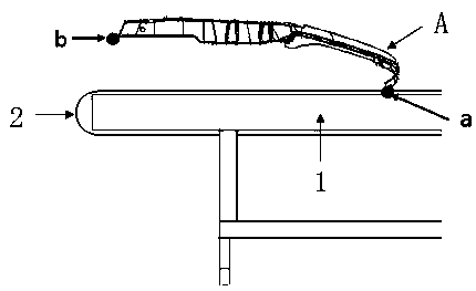
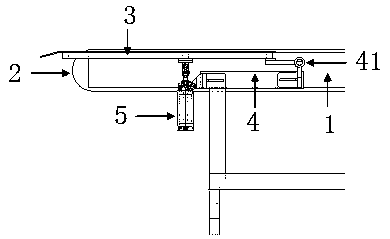
[0019] Such as Figure 3-5 , The flexible auxiliary tooling of the present invention includes a wire tail conveying platform 1, a conveyor belt 2 is provided on the wire tail conveying platform 1, and a material receiving plate 3 with an adjustable inclination is provided on the conveyor belt 2.

[0020] In the flexible auxiliary tooling of the present invention, an adjustable inclination receiving plate 3 is provided on the conveyor belt 2 of the end-of-line conveying platform 1. Before the stamping part A with a large drop is produced, the inclination of the receiving plate 3 is small or even close to At zero, th...


PUM


Abstract

The invention provides a flexible auxiliary tool. The flexible auxiliary tool can solve the problem of deformation of a stamping part with large fall put at the tail portion of a production line. Theflexible auxiliary tool comprises a line tail conveying table, a conveying belt is arranged on the line tail conveying table, and the key is that a material receiving plate with the adjustable inclination is arranged on the conveying belt. According to the flexible auxiliary tool, when the stamping part is put down by a line tail manipulator, due to the support protection of the material receivingplate, it is guaranteed that the fall difference of the falling points at the front end and the rear end of the stamping part is not large obviously, so that the situation that shaking deformation occurs when the stamping part falls is avoided, and finally the high-quality qualified stamping part is guaranteed. Due to the fact that the inclination of the material receiving plate is adjustable, discharging and receiving of stamping parts with different height falls can be adapted, and the flexible auxiliary tool has the flexibility characteristics and is high in universality.

Description

technical field [0001] The invention relates to the technical field of auxiliary tooling for stamping equipment of automobile stamping parts, in particular to a flexible auxiliary tooling. Background technique [0002] In the current stamping equipment, after the stamping parts with a large drop are placed by the manipulator at the end of the production line, due to the large drop between the front and rear sides of the stamping parts, the stamping parts fall and shake and deform when they fall onto the pulley, which seriously affects the quality of the stamping parts. , leading to a high scrap rate of stamping parts and increasing the cost of vehicle development. This is because the end-of-line manipulator of the existing stamping equipment cannot rotate the angle after grabbing the stamping part. After the stamping part is released, the stamping part is only conveyed by the horizontal pulley, and the angle of the pulley cannot be adjusted. The structure of the existing ma...

Claims


Application Information

Patent Timeline
Patent Type & Authority Applications(China)
IPC IPC(8): B21D43/12
CPCB21D43/12
Inventor 郭道树徐磊彭本栋
Owner CHERY AUTOMOBILE CO LTD
Why Eureka
Try Eureka