Movement navigator for large equipment

A large-scale equipment and navigator technology, applied in the field of navigation, can solve the problems of large-scale equipment that are difficult to locate accurately, and achieve the effects of reducing the time and effort of repeated adjustments, accurate positioning, and a wide range of applications

Pending Publication Date: 2017-12-22
SIHONG ZHENGXING MEDICAL TECH CO LTD
View PDF5 Cites 0 Cited by
  • Summary
  • Abstract
  • Description
  • Claims
  • Application Information

AI Technical Summary

Problems solved by technology

[0007] The purpose of the present invention is to provide a mobile navigator for large-scale equipment to solve the problem in the prior art that it is difficult to accurately locate large-scale equipment when it moves

Method used


Image

  • Movement navigator for large equipment
  • Movement navigator for large equipment
  • Movement navigator for large equipment

Examples


Embodiment 1

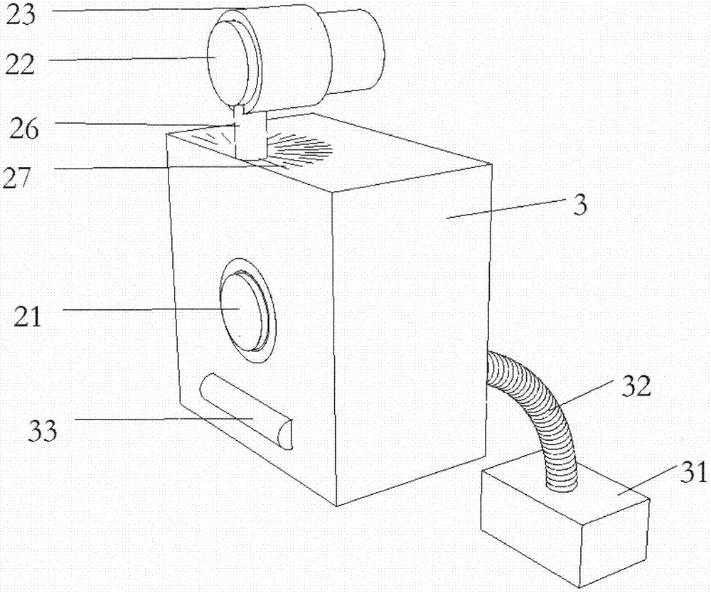
[0039] Such as figure 1 Shown is the large-scale equipment mobile navigator described in the present invention, including a control unit 1, an execution unit 2 and a housing 3, the control unit 1 is a hand control device, and the execution unit 2 includes two linear laser emitters, one of which is located in the housing 3, the other is located outside the housing 3, connected to the housing 3 through a rotating shaft.

[0040] Surgical robots are bulky. In order not to occupy space, they are generally placed in a corner of the operating room when not in use, facing the operating bed, and cannot make large turns on the spot. They need to be moved out of the corner before they can be easily pushed. There is a driving motor inside it, and it can move forward by itself after pressing the control switch. The operator controls the direction control handle on the back of the surgical robot with both hands, controlling its forward direction like driving an electric bicycle. When the...

Embodiment 2

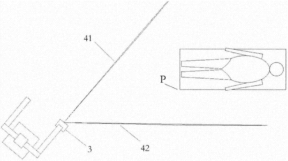
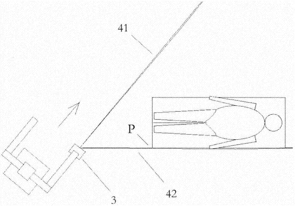
[0048] Such as Figure 5, the present embodiment uses a navigator with only a single fixed laser emitter. The difference between this embodiment and the first embodiment is that there is no rotating laser transmitter, and it needs to be used when the surrounding space is large and can be turned on the spot. The method for adjusting the level of the instrument is the same as in Embodiment 1. When the surgical robot is figure 2 In the position, if the surrounding space is large, the surgical robot can be pushed to turn right on the spot, so that the fixed laser 41 can be irradiated to point P. Then push the surgical robot forward until the right front wheel reaches point P, and then push the surgical robot to turn right on the spot, so that the fixed laser 41 is parallel to the edge of the bed, and the position required for the operation is reached.

Embodiment 3

[0050] Such as Image 6 , the present embodiment uses a navigator with a laser reflective surface. The structure of this embodiment is similar to that of Embodiment 1, the difference is that the rotating laser emitter 22 is fixed in the casing 3 and arranged parallel to the fixed laser 21 up and down. There is a laser reflective surface 24 perpendicular to the horizontal plane in front of the rotating laser emitter 22 , and the laser reflective surface 24 is connected to a horizontal support 25 via a rotating shaft 26 . The linear laser emitted by the rotating laser emitter 22 is reflected by the laser reflecting surface 24 to form a rotating laser 42 .

[0051] The navigation steps in this embodiment are the same as those in Embodiment 1.


PUM


Abstract

The invention discloses a movement navigator for large equipment. The movement navigator for the large equipment comprises a control unit, an execution unit and a shell; the execution unit comprises laser emitters and a laser angle controller. By means of the movement navigator for the large equipment, by emitting indication laser and controlling the indication angle of the laser, the problem that in the prior art, the large equipment is difficult to accurately position and needs to be adjusted repeatedly when being moved is solved. The movement navigator for the large equipment is wide in application range, is less affected by the initial position and angle where the equipment is located, is convenient to mount and dismount and accurate in positioning and capable of saving time and energy needed to repeatedly adjust the large equipment during movement.

Description

technical field [0001] The invention belongs to the technical field of navigation, in particular to a mobile navigator for large equipment. Background technique [0002] In daily work, some large-scale equipment needs to be moved when used, and must be moved to the designated position accurately. In medical operations, the positioning accuracy of the equipment is particularly high. Large-scale equipment is heavy and the wheels are generally small. Due to infrequent movement, the wheel shaft is prone to deformation and lack of lubrication in the long run, and it is laborious to move. Moreover, large-scale equipment is generally used in a small room, which is inconvenient to adjust the direction and difficult to accurately locate. [0003] Taking the Da Vinci surgical robot as an example, the preoperative preparation for robotic surgery is very demanding. It needs to install special instrument sets, calibration lenses, self-machine and robot arm installation, etc. Among them,...

Claims


Application Information

Patent Timeline
Patent Type & Authority Applications(China)
IPC IPC(8): B25J19/02B25J13/08
CPCB25J13/088B25J19/022
Inventor 郑杨郑兴
Owner SIHONG ZHENGXING MEDICAL TECH CO LTD
Why Eureka
Try Eureka