Automatic injection molding feeding device

A feeding device and feeding mechanism technology, applied in the direction of coating, etc., can solve the problems of employee safety threats, harsh working environment, high processing temperature, etc.

Pending Publication Date: 2017-12-22
精英塑胶(珠海)有限公司
View PDF4 Cites 6 Cited by
  • Summary
  • Abstract
  • Description
  • Claims
  • Application Information

AI Technical Summary

Problems solved by technology

[0002] In the current injection molding field, materials are usually picked up by three-axis manipulators, and some molds with complex structures, many rows and core-pulling mechanisms can only be picked up by hand.
Some injection molding products need to put metal inserts inside the product, and the position of the metal inserts needs to be placed very accurately. It is difficult to achieve the required accuracy with ordinary manipulators. The existing technology uses manual placement, resulting in longer injection molding cycles.
Secondly, the processing temperature of the mold is very high, some places exceed 110 degrees Celsius, and the working environment is very harsh. It is easy to burn the workers when placing the metal inserts manually, and the safety of the employees is threatened.

Method used


Image

  • Automatic injection molding feeding device
  • Automatic injection molding feeding device
  • Automatic injection molding feeding device

Examples


Embodiment Construction

[0020] The idea, specific structure and technical effects of the present invention will be clearly and completely described below in conjunction with the embodiments and accompanying drawings, so as to fully understand the purpose, features and effects of the present invention. Apparently, the described embodiments are only some of the embodiments of the present invention, rather than all of them. Based on the embodiments of the present invention, other embodiments obtained by those skilled in the art without creative efforts belong to The protection scope of the present invention.

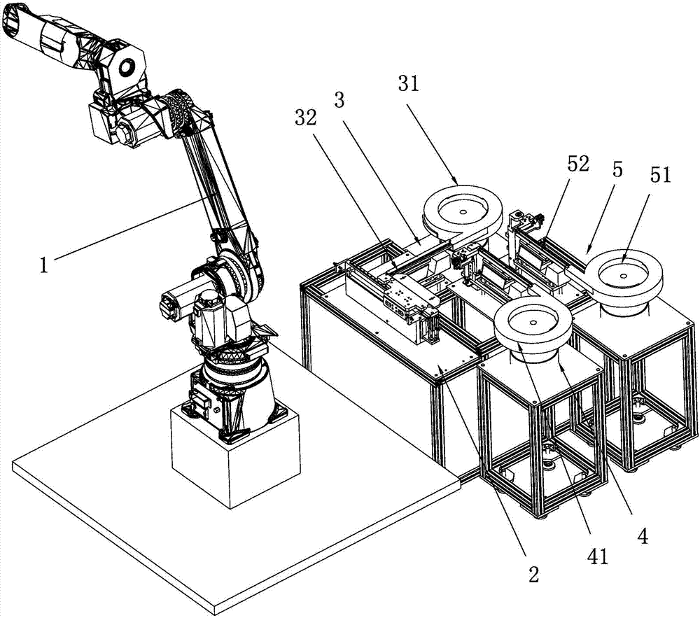
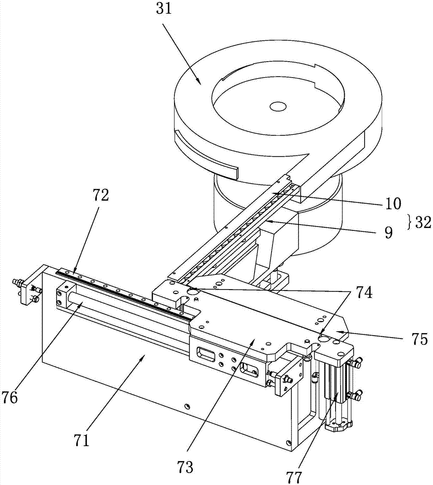
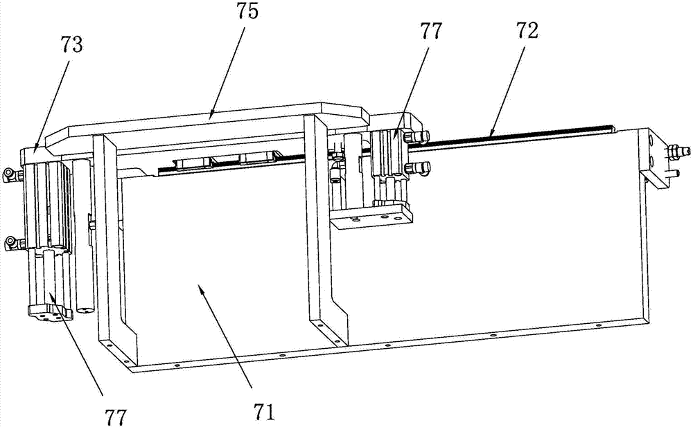
[0021] refer to Figure 1 to Figure 5 , an automatic injection molding feeding device, comprising a manipulator 1, a workbench 2 is arranged beside the manipulator 1, a sucker is arranged on the manipulator 1, a workpiece suction head is arranged on the sucker, and a workbench 2 is arranged on the workbench 2 The first feeding mechanism 3, the second feeding mechanism 4 and the third feeding mech...


PUM


Abstract

The invention discloses an automatic injection molding feeding device. The automatic injection molding feeding device comprises a manipulator; a workbench is arranged beside the manipulator which is provided with a suction cup; a workpiece suction head is arranged on the suction cup; a first feeding mechanism, a second feeding mechanism and a third feeding mechanism are arranged on the workbench; the first feeding mechanism comprises a first vibration disk; a discharging port of the first vibration disk is connected with a first discharging groove which is connected with a discharging mechanism; the second feeding mechanism comprises a second vibration disk; the third feeding mechanism comprises a third vibration disk; the tail ends of the second discharging groove and a third discharging groove are each provided with a positioning mechanism; the manipulator stretches into a mold and is used for placing inserts to assigned positions in a mold core; after mold closing is completed, the mold is taken out through the manipulator to complete on injection molding cycle; and manual operation is not needed in the whole injection molding feeding process, machining is more efficient, the manipulator is not affected by high temperature, and the safety of employees is protected.

Description

technical field [0001] The invention relates to the field of injection molding equipment, in particular to an automatic injection molding feeding device. Background technique [0002] In the current injection molding field, three-axis manipulators are usually used to pick up materials, and some molds with complex structures, many rows and core-pulling mechanisms can only be picked up by hand. Some injection molding products need to put metal inserts inside the product, and the position of the metal inserts needs to be placed very accurately. It is difficult to achieve the required accuracy with ordinary manipulators. The existing technology uses manual placement, resulting in longer injection molding cycles. . Secondly, the processing temperature of the mold is very high, exceeding 110 degrees Celsius in some places, and the working environment is very harsh. It is easy to burn workers when placing metal inserts manually, and the safety of employees is threatened. In view ...

Claims


Application Information

Patent Timeline
Patent Type & Authority Applications(China)
IPC IPC(8): B29C45/14
CPCB29C45/14008
Inventor 常立峰田俊聂勤周少凡
Owner 精英塑胶(珠海)有限公司
Why Eureka
Try Eureka