Composite steel roller

A composite steel and roll body technology, applied in the field of composite steel rolls, can solve problems such as complex structures

Inactive Publication Date: 2017-12-22
瑞安市博威机械配件有限公司
View PDF7 Cites 2 Cited by
  • Summary
  • Abstract
  • Description
  • Claims
  • Application Information

AI Technical Summary

Problems solved by technology

[0002] During the compounding process of the compounding machine, the compounding steel roller and the pressure roller should be kept in tight contact. When compounding some special compounding materials (such as built-in film chips), they often need different compounding temperatures in different positions to meet the requirements of their materials. Requirements, the current method can only use multiple composite processes before and after, that is, to set multiple composite steel rolls, the structure is very complicated

Method used


Image

  • Composite steel roller

Examples


Embodiment Construction

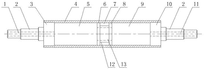
[0010] As shown in the figure, the composite steel roll of the present invention includes a roll body 4, the roll body 4 is a hollow tube, the two ends of the roll body 4 are fixedly provided with a left end cover 3 and a right end cover 10, and the outer end faces of the left and right end covers are fixedly connected to the left and right sides. The roller shaft 2, the inner hole of the roller body 4 is provided with a left partition 6 and a right partition 8 in the middle position, and a middle closed cavity 7 is formed between the left and right partitions, and the left partition 6 and the left end cover 3 The left closed cavity 5 is surrounded, and the right closed cavity 9 is surrounded between the right partition 8 and the right end cover 10. The left and right closed cavities communicate through the tube hole 13, and the tube sleeve 12 with the tube hole 13 is closed from the middle. The middle of the body 7 runs through and its two ends are respectively fixed on the le...


PUM


Abstract

The invention discloses a composite steel roller, comprising a roller body; the roller body is a hollow tube; a left end cover and a right end cover are respectively and fixedly arranged at the two ends of the roller body; the outer end faces of the left end cover and the right end cover are respectively and fixedly connected with a left roller shaft and a right roller shaft; the composite steel roller is characterized in that a left spacer plate and a right spacer plate are arranged in the middle position of an inner hole of the roller body, and a middle closed cavity is defined by the left spacer plate and the right spacer plate; a left closed cavity is defined by the left spacer plate and the left end cover, and a right closed cavity is defined by the right spacer plate and the right end cover; the left closed cavity and the right closed cavity are communicated with each other by means of a pipe hole; a pipe sleeve provided with the pipe hole passes through the middle of the middle closed cavity, and the two ends of the pipe sleeve are respectively fixed on the left spacer plate and the right spacer plate; a separation distance is reserved between the excircle of the pipe sleeve and the inner hole of the roller body; a left roller shaft is provided with a left axial hole so as to enable the left closed cavity to be communicated with cooling inflow water, and a right roller shaft is provided with a right axial hole so as to enable the right closed cavity to be communicated with cooling discharge water. Only the two ends of the roller body of the composite steel roller can be cooled, so that the requirements of a special composite work are more widely met.

Description

technical field [0001] The invention relates to a composite equipment accessory, in particular to a composite steel roll of a composite machine. Background technique [0002] During the compounding process of the compounding machine, the compounding steel roller and the pressure roller should be kept in tight contact. When compounding some special compounding materials (such as built-in film chips), they often need different compounding temperatures in different positions to meet the requirements of their materials. Requirements, the present method can only be to adopt front and rear multi-channel composite process, promptly will set up a plurality of composite steel rolls, and the structure is very complicated. Contents of the invention [0003] Aiming at the deficiency of the background technology, the object of the present invention is to provide a composite steel roller which can make the roller body only be cooled at both ends, so as to more widely meet the requiremen...

Claims


Application Information

Patent Timeline
Patent Type & Authority Applications(China)
IPC IPC(8): B32B37/10B32B37/08
CPCB32B37/08B32B37/10
Inventor 薛迪媚
Owner 瑞安市博威机械配件有限公司
Why Eureka
Try Eureka