Vacuum circuit breaker force reducing device

A technology of vacuum circuit breaker and vacuum tube, applied in high-voltage air circuit breaker, circuit, high-voltage/high-current switch, etc., can solve the problems of overall complexity, reduced service life, and cumbersome replacement.

Active Publication Date: 2020-05-29
JIANGXI TUOWANG ELECTRIC
View PDF4 Cites 0 Cited by
  • Summary
  • Abstract
  • Description
  • Claims
  • Application Information

AI Technical Summary

Problems solved by technology

A vacuum circuit breaker usually includes a bracket, a vacuum tube and a switchgear. The vacuum tubes are erected side by side on the bracket. The vacuum tube is provided with a connecting rod for opening and closing the vacuum tube. The connecting rod moves into the vacuum tube to make the vacuum tube close and conduct. The movement of the vacuum tube makes the vacuum tube open and disconnected. Generally, the connecting rod is equipped with a reset spring for resetting the connecting rod to the position of the vacuum tube open. The switch cabinet is equipped with a permanent magnet operation box or a mechanical operation box. The drive mechanism It usually includes driving parts, which are connected with the permanent magnet control box or the output shaft of the mechanical operation box. However, in the opening and closing operation of the vacuum circuit breaker, especially in the process of opening and resetting, in order to ensure the reset, the reset pull The force of the spring is usually large, which makes the transmission structure parts in the permanent magnet operation box or mechanical operation box easy to wear and reduce the service life, and there are many parts in the permanent magnet operation box or mechanical operation box, and the whole is more complicated , when subjected to the impact of opening and reset, it is easy to damage the internal parts and reduce the service life of the equipment, and it is difficult to replace the parts in the switchgear, and the replacement after damage is cumbersome, which affects the use efficiency of the equipment

Method used


Image

  • Vacuum circuit breaker force reducing device
  • Vacuum circuit breaker force reducing device
  • Vacuum circuit breaker force reducing device

Examples


Embodiment 1

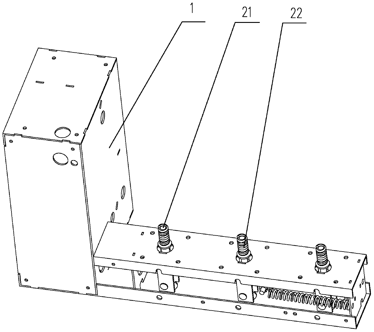
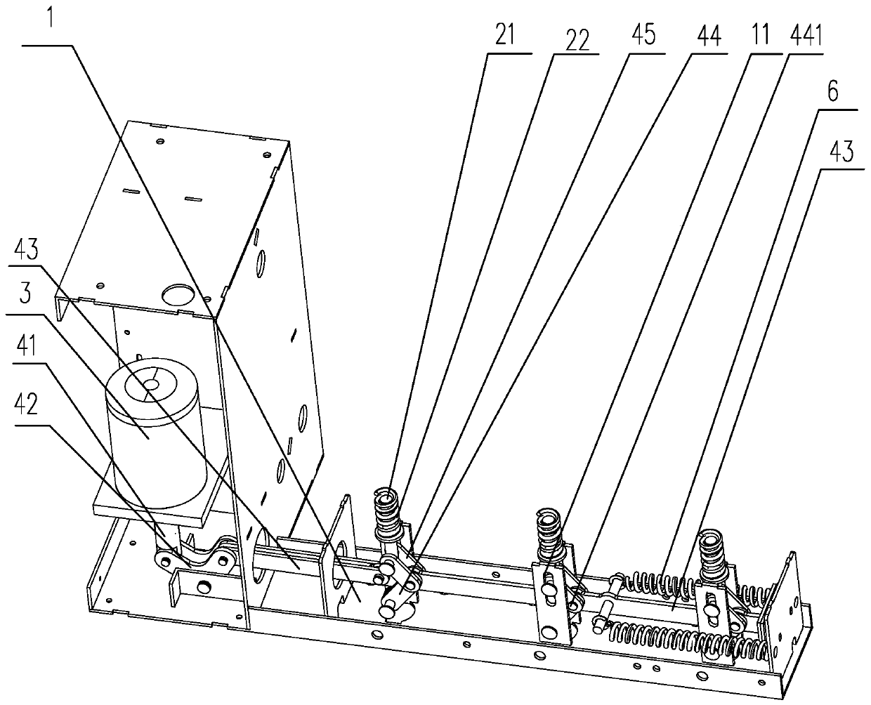
[0018] Example one: by figure 1 , figure 2 It can be seen that the present invention discloses an embodiment of a vacuum circuit breaker force reducing device, which includes a bracket 1, a plurality of vacuum tubes, and a driving mechanism for driving the vacuum tubes to open and close, and the vacuum tubes are arranged on the bracket 1 at intervals, The vacuum tube is respectively provided with a connecting rod 21 for opening and closing the vacuum tube, the connecting rod 21 is sleeved with a reset extension spring 22 for resetting the connecting rod 21 to the opening position of the vacuum tube, and the driving mechanism includes a drive Part 3, a crank arm 42 and a transmission rod 41, the driving part 3 is in transmission connection with the transmission rod 41, the crank arm 42 is hingedly arranged on the support 1 and is in transmission connection with the transmission rod 41, and the crank arm 42 is also connected There is a main shaft 43 used to drive the vacuum tube ...

Embodiment 2

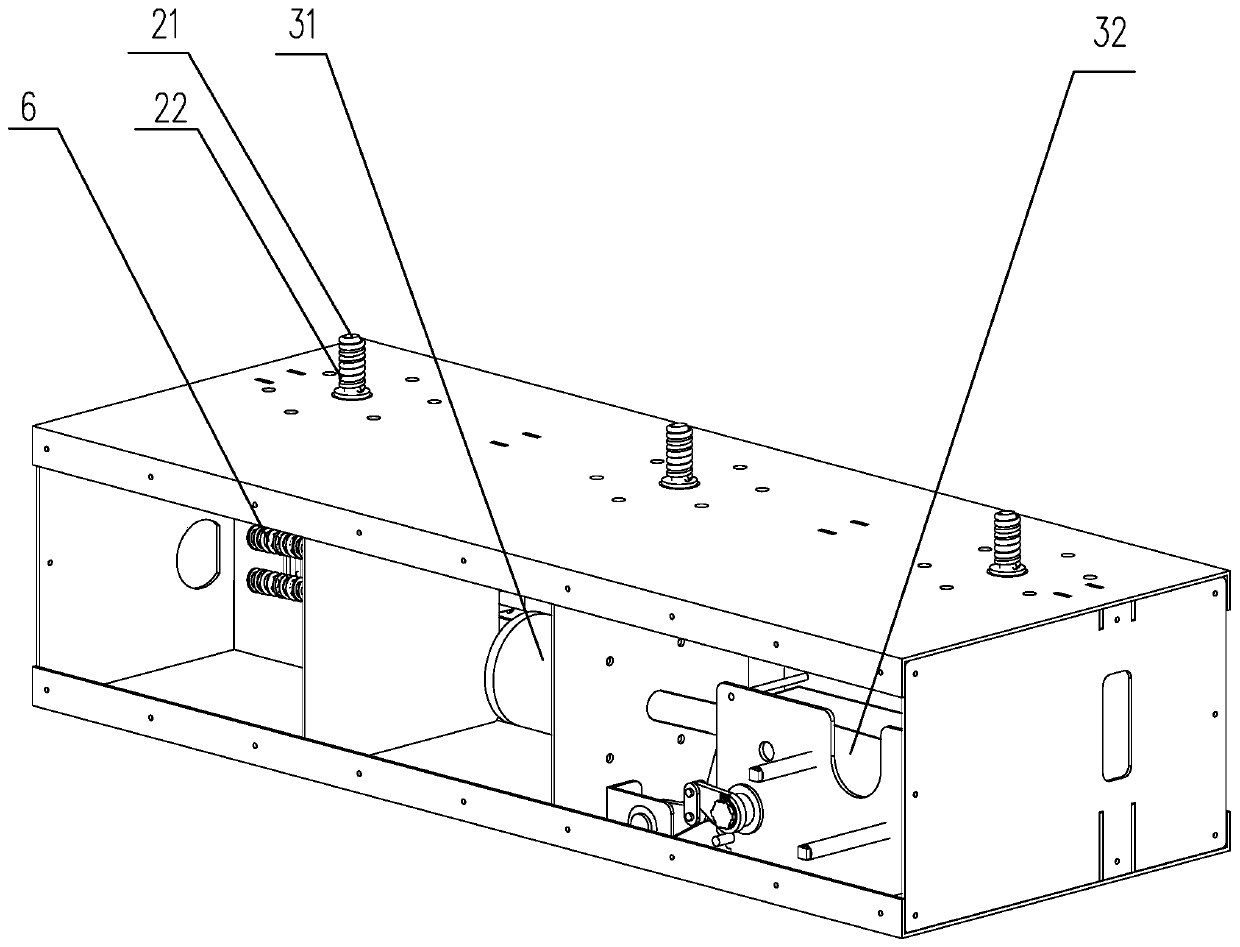
[0019] Example two: by image 3 , Figure 4 It can be seen that the present invention discloses another embodiment of a vacuum circuit breaker force reducing device, which includes a bracket 1, a plurality of vacuum tubes, and a driving mechanism for driving the vacuum tube to open and close. The vacuum tubes are arranged on the bracket 1 at intervals , The vacuum tube is respectively provided with a connecting rod 21 for opening and closing the vacuum tube, the connecting rod 21 is sleeved with a reset tension spring 22 for resetting the connecting rod 21 to the opening position of the vacuum tube, and the driving mechanism includes The driving part 3, the turning arm 42, the transmission rod 41 and the transmission group for driving the turning arm 42 to rotate, the driving part 3 includes a permanent magnet operation box 31 and a mechanical operation box 32, and the driving rod includes a first driving rod 52 And the second driving rod 53, the permanent magnet operating box ...


PUM


Abstract

The invention discloses a vacuum circuit breaker force reducing device, which comprises a support, vacuum tubes and a driving mechanism. The vacuum tubes are arranged on the support at intervals; and each vacuum tube is provided with a connecting rod. The driving mechanism comprises a driving member, a crank and a drive rod. The driving member is in drive connection with the drive rod; the crank is in drive connection with the drive rod; the crank is also connected with a main shaft; the main shaft is slidably arranged on the support; the main shaft is provided with a lower swing arm and an upper swing arm; and one end of the lower swing arm is hinged with the main shaft through a first hinge shaft, and the other end thereof is hinged with the support. The support is provided with a first slide groove in the place corresponding to the lower swing arm; each connecting rod is in same-direction arrangement with the first slide groove; and one end of the upper swing arm is connected with the connecting rod and is slidably arranged in the first slide groove along the first slide groove, and the other end is hinged to the main shaft through the first hinge shaft. The device reduces wear of parts in a switch cabinet in opening-closing operation of a vacuum tube, and prolongs the overall service life of the device.

Description

Technical field [0001] The invention relates to the technical field of power systems, and in particular to a force reducing device in a vacuum circuit breaker opening and closing structure. Background technique [0002] The vacuum circuit breaker is named after its arc extinguishing medium and the insulating medium of the contact gap after the arc extinguishing are high vacuum; it has the advantages of small size, light weight, suitable for frequent operation, and no need to overhaul the arc extinguishing. Chinese applications are more popular. A vacuum circuit breaker usually includes a bracket, a vacuum tube and a switch cabinet. The vacuum tubes are arranged side by side on the bracket. The vacuum tube is provided with a connecting rod for opening and closing the vacuum tube. Moving the connecting rod into the vacuum tube makes the vacuum tube close and conduct. When the vacuum tube moves outside, the vacuum tube is opened and disconnected. The connecting rod is generally equ...

Claims


Application Information

Patent Timeline
Patent Type & Authority Patents(China)
IPC IPC(8): H01H33/666
CPCH01H33/666
Inventor 虞旭海
Owner JIANGXI TUOWANG ELECTRIC
Why Eureka
Try Eureka