Flat linear motor

A linear motor and flat technology, applied in the field of flat linear motors, can solve the problems of high difficulty in processing and assembly, complex structure, large overall size of the motor, etc., and achieve the effects of reducing production costs, simplifying the overall structure, and simplifying the motor structure

Active Publication Date: 2017-12-22
浙江史笛威电子有限公司
View PDF2 Cites 3 Cited by
  • Summary
  • Abstract
  • Description
  • Claims
  • Application Information

AI Technical Summary

Problems solved by technology

[0005] (1) The existing linear motor has many components and a complex structure, which leads to a large overall size of the motor; due to factors such as the battery life of the mobile phone, the internal space is limited, and the accessories in the mobile phone can be small or small, and can be integrated. The vibration motor is also Its dimensions must be controlled, and existing linear motors cannot meet this requirement;
[0006] (2) In order to control the vibration amplitude of the vibrating elements, most of them use me

Method used


Image

  • Flat linear motor
  • Flat linear motor
  • Flat linear motor

Examples


Embodiment 1

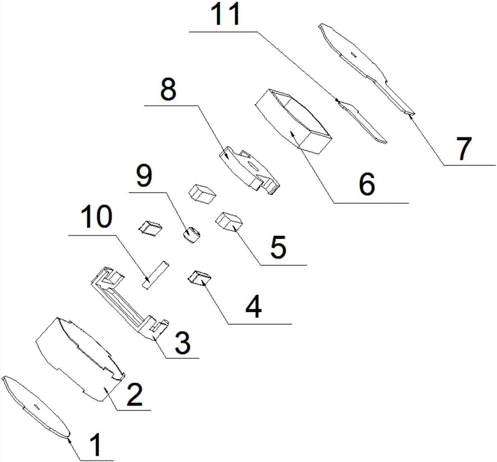
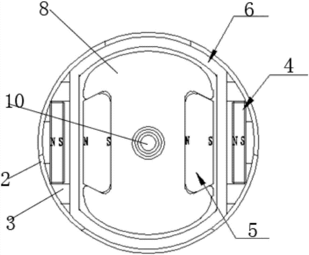
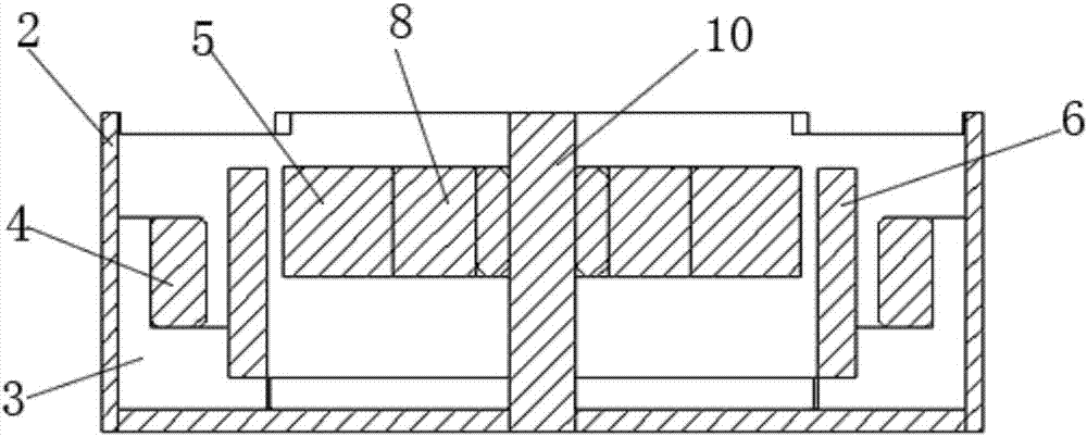
[0047] refer to Figure 1-4 , a flat linear motor of the present invention, including a housing, the housing is provided with a stator 02, a mover 01 and a single shaft 10, the single shaft 10 is installed in the center of the mover, the stator includes a driving coil 6, and the driving coil is wound The mover is set in one circle; there are at least two pairs of magnets between the stator 02 and the mover 01; each pair of magnets includes a driving positioning magnet 5 and a positioning magnet 4, and the driving positioning magnet 5 is set on the moving element, and the driving positioning magnet 5 is opposite to the positioning magnet 4, and the position of the positioning magnet 4 is fixed relative to the shell.

[0048] When the linear motor is working, the driving coil 6 is energized and generates an electromagnetic field, and the mover including the driving positioning magnet 5 is located in the electromagnetic field, and the driving positioning magnet 5 is pushed by the...

Embodiment 2

[0067] refer to Figure 5 , this embodiment is a modification made on the basis of embodiment 1, the details are as follows.

[0068] In this embodiment, the flat linear motor is flat and square as a whole, and the housing is also square.

[0069] In this embodiment, four driving and positioning magnets 5 are included, and the four driving and positioning magnets 5 are evenly distributed around the outer ring of the copper 8; further, the four driving and positioning magnets 5 form a ring structure, and the ring structure is directly sleeved on the On the outer ring of copper 8. The fixing method of the magnet has a simple structure and is convenient for installation.

[0070] In this embodiment, four positioning magnets 4 are correspondingly arranged; since the housing is square, in order to adapt to the shape of the housing, this embodiment directly arranges four positioning magnets 4 on the four corners of the housing, and Drive positioning magnet 5 relative.

[0071] I...


PUM


Abstract

The invention discloses a flat linear motor, which comprises a housing. The housing is internally provided with a stator, a rotor and a single shaft. The single shaft passes through the center of the rotor. The stator comprises a driving coil, wherein the driving coil is wound around the rotor. At least two pairs of magnets are arranged between the stator and the rotor. Each pair of magnets comprise a drive positioning magnet and a positioning magnet, wherein the drive positioning magnet is arranged on the rotor; the drive positioning magnet is arranged opposite to the positioning magnet; and the positioning magnet is fixed corresponding to the housing. When powered on, the driving coil drives the rotor provided with the drive positioning magnet to be in reciprocating rectilinear movement along the single shaft; and meanwhile, the attraction force between the drive positioning magnet and the positioning magnet enables the rotor to keep horizontal in the same horizontal plane. The drive positioning magnet integrates functions of driving the rotor and keeping balance of the rotor, thereby greatly simplifying overall structure of the linear motor, and facilitating reducing the size of the linear motor.

Description

technical field [0001] The invention relates to the technical field of electronic products, in particular to a flat linear motor. Background technique [0002] With the rapid development of portable devices such as smart phones, the requirements for the electrical devices installed in them are getting higher and higher. [0003] In order to achieve the purpose of saving space and improving quality, electronic components are gradually developing in the direction of ultra-small and ultra-thin. As the main implementer of effects such as caller ID and touch feedback, vibrators also put forward higher requirements. Linear vibrating motors have replaced other vibrators because of their strong advantages in the height direction. [0004] There are many linear vibration motors currently used in smartphones, but most of them have the following disadvantages: [0005] (1) The existing linear motor has many components and a complex structure, which leads to a large overall size of th...

Claims


Application Information

Patent Timeline
IPC IPC(8): H02K33/02H02K41/03
CPCH02K33/02H02K41/03
Inventor 江文明魏义祥
Owner 浙江史笛威电子有限公司
Why Eureka
Try Eureka