Multi-protection pulse current source

A pulse current, multiple protection technology, applied in the field of electronics, can solve the problems of single machine work, can not be dealt with in time, does not have overcurrent protection and other problems

Inactive Publication Date: 2017-12-22
CHANGCHUN INST OF TECH
View PDF6 Cites 6 Cited by
  • Summary
  • Abstract
  • Description
  • Claims
  • Application Information

AI Technical Summary

Problems solved by technology

[0004] However, the technology disclosed in the patent ZL201210120267.5 is completely realized based on the analog circuit. This circuit has many disadvantages: 1. It cannot realize program control, it can only work on a single machine, and cannot interact with the ECU of the automobile system; 2. It is controlled by the analog circuit. The repetition frequency of the constructed pulse trigger circuit is easily affected by environmental factors such as temperature, thereby affecting t

Method used


Image

  • Multi-protection pulse current source
  • Multi-protection pulse current source
  • Multi-protection pulse current source

Examples


Example Embodiment

[0038] Example 1 Overall structure of the system

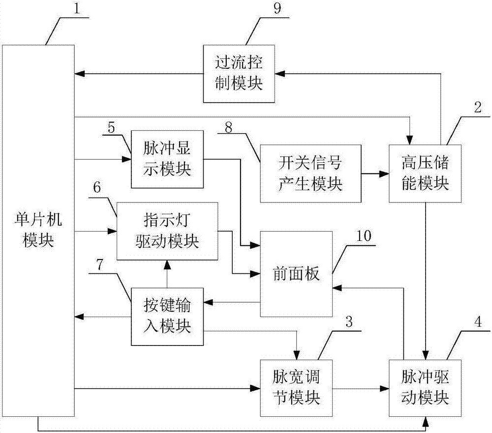
[0039] like figure 1 As shown, the system structure includes a single-chip microcomputer module 1, a high-voltage energy storage module 2, a pulse width adjustment module 3, a pulse drive module 4, a pulse display module 5, an indicator light drive module 6, a key input module 7, a switch signal generation module 8, a Flow control module 9 and front panel 10.

Example Embodiment

[0040] Embodiment 2 SCM module

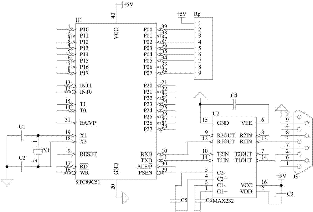
[0041] like figure 2 As shown, the structure of the single-chip microcomputer module 1 is that the port VCC and port GND of the single-chip microcomputer U1 are respectively connected to +5V power supply and digital ground, the crystal oscillator Y1 is connected between the port X1 and the port X2, and the port X1 and the port X2 are also connected through the capacitor C1. And capacitor C2 is connected to digital ground, common terminal 1 of resistance Rp is connected to +5V power supply, other pins are respectively connected to ports P00~P07 of microcontroller U1, port VCC and port GND of level conversion chip U2 are respectively connected to +5V power supply and digital ground, port VDD is connected to +5V power supply through capacitor C3, port VEE is connected to digital ground through capacitor C4, capacitor C5 is connected between port C2+ and port C2-, capacitor C6 is connected between port C1+ and port C1-, port T1IN and port R1OUT C...

Example Embodiment

[0043] Embodiment 3 Switch signal generation module

[0044] like Figure 9 As shown, the structure of the switch signal generating module 8 is as follows: the port VCC and port GND of the 555 timer U12 are connected to the +5V power supply and the digital ground respectively, the port RST is connected to the +5V power supply, and the port DISC is connected to the +5V power supply through the resistor R32. , the port DISC is connected to the port THR and the port TRIG through the resistor R33, the port TRIG is connected to the digital ground through the capacitor C24, the port CVOLT is connected to the digital ground through the capacitor C25, and the port OUT is used as the output of the switch signal generation module 8. The model of 555 timer U12 is TLC555;

[0045] The switching signal generating module 8 is used for generating a square wave with a frequency of 35.37 kHz and a duty ratio of 85.1%, and provides a switching signal for the high-voltage energy storage module ...


PUM


Abstract

The invention, which belongs to the technical field of the electronic technology, provides a multi-protection pulse current source comprising a single-chip microcomputer module (1), a high-voltage energy storage module (2), a pulse width modulation module (3), a pulse drive module (4), a pulse display module (5), an indicating lamp driving module (6), a key input module (7), a switch signal generating module (8), an over-current control module (9) and a front panel (10). Control is realized by the single-chip microcomputer; the usage becomes flexible; the functions are enriched; upgrading and updating become convenient; and the output pulse shape is good. Besides, the multi-protection pulse current source has multi-protection functions of power-ne impact protection, over-current protection, and current-limiting protection and the like; and the usage safety is high.

Description

technical field [0001] The present invention belongs to the technical field of electronic technology. In particular, it relates to a pulse current source with overcurrent and current limiting protection. Background technique [0002] Pulsed current sources play an important role in the fields of laser radar, laser ranging, laser processing, and automotive electronics. For example, in automotive electronic systems, the primary ignition coil, electronic ignition timing circuit, exhaust gas recirculation control valve (EGR), fuel injectors and other solenoid valves all require pulsed current sources. The performance of the pulse current source directly affects its reliability in the system. In the automotive electronic system, there are high requirements on the drive capability of the pulse current and pulse width control. In addition, because the automotive system is a precision system, the current limiting and overcurrent protection of the device are particularly important....

Claims


Application Information

Patent Timeline
IPC IPC(8): H02M11/00H02M1/32
CPCH02M1/32H02M11/00
Inventor 黄丫田小建段春丽于兰王双印汝玉星王亚杰
Owner CHANGCHUN INST OF TECH
Why Eureka
Try Eureka