Supercharge Your Innovation With Domain-Expert AI Agents!

Multi-mode control device based on television LED lamp

A technology of LED lights and control devices, applied in the field of TV, can solve the problems of power consumption, increase the standby power consumption of TVs, increase the standby power consumption of products, etc., and achieve the effect of reducing standby power consumption

Inactive Publication Date: 2017-12-22
AMOLOGIC (SHANGHAI) CO LTD
View PDF3 Cites 2 Cited by
  • Summary
  • Abstract
  • Description
  • Claims
  • Application Information

AI Technical Summary

Problems solved by technology

[0004] However, there are many disadvantages in the control of LED lights following the same mode in various scenarios. For example, in shopping malls, some TV LED lights have the manufacturer's LOGO, and the manufacturer hopes that the LED lights are on to present their respective brands in the store. However, according to the rule that the LED light is off during standby, it obviously cannot meet the needs of the manufacturer; in the family, if the TV is placed in the living room, according to the rule that the LED light is on during standby, although it plays a role in reminding the user that the TV is in standby , but the use of ordinary LED lights to turn on and turn on the brightness increases the standby power consumption of the TV; Turning on the brightness will be dazzling, affecting the user's rest, and also consumes unnecessary power, increasing the standby power consumption of the product
[0005] There are limitations in controlling the on and off of LED lights in the existing single mode, which cannot meet the user's needs for LED on-off control in different scenarios, nor can it meet the requirements for adjusting the brightness of the LED on and off in different scenarios.

Method used


Image

  • Multi-mode control device based on television LED lamp

Examples


Embodiment Construction

[0039] It should be noted that, in the case of no conflict, the following technical solutions and technical features can be combined with each other.

[0040] The specific embodiment of the present invention will be further described below in conjunction with accompanying drawing:

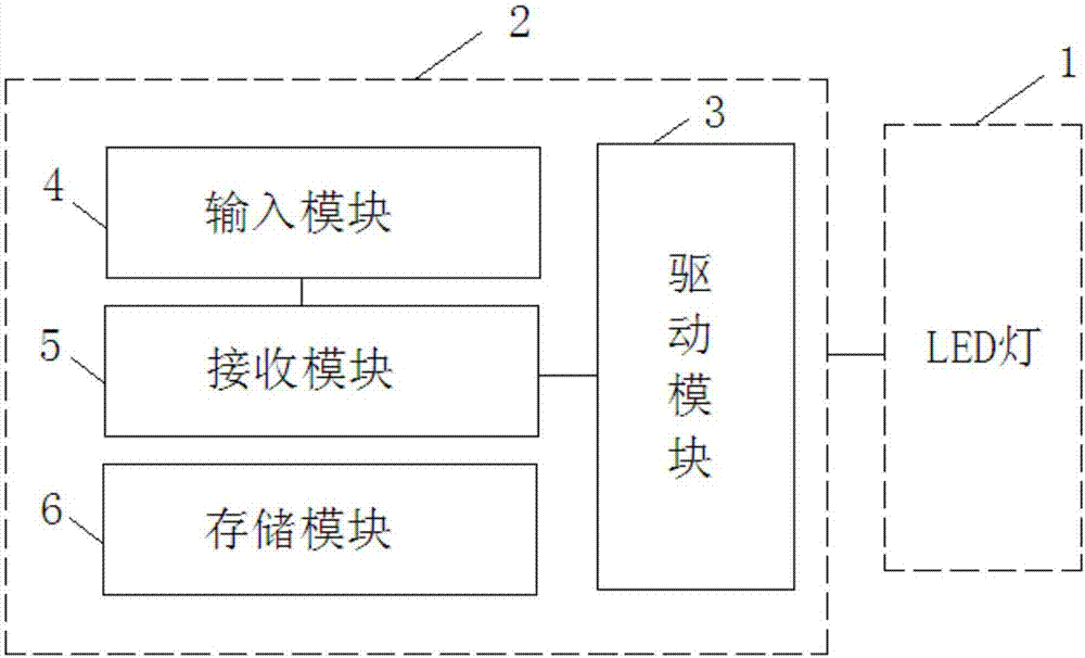
[0041] Such as figure 1 As shown, a multi-mode control device based on TV LED lamps, the above-mentioned multi-mode control device 2 is connected to the above-mentioned LED lamp 1, and the above-mentioned multi-mode control device 2 includes:

[0042] An input module 4, the above-mentioned input module 4 is used to provide and output the user input mode selection information and state transition information;

[0043] A receiving module 5, the receiving module 5 is connected to the input module 4, and the receiving module 5 is used to receive and output the above-mentioned mode selection information and the above-mentioned state transition information;

[0044] Storage module 6, the above-mentione...


PUM


Abstract

The invention provides a multi-mode control device based on a television LED lamp. The multi-mode control device connected with an LED lamp comprises an input module, a receiving module, a storage module, and a drive module. The receiving module connected with the input module is used for receiving mode selection information and state conversion information and outputting the received information. The storage module is used for storing a plurality of control strategies corresponding to a plurality of modes. The drive module connected with the receiving module and the storage module is used for receiving the mode selection information and state conversion information, invoking a corresponding control strategy from the storage module according to the mode selection information, and controlling turning on / off and the luminance of the LED lamp by adjusting a duty ratio based on the control strategy and the state conversion information. The multi-mode control device has the following beneficial effects: different control strategies are employed under various control modes; the LED control need of the user in different scenes is met; on the basis of multi-mode control, the turning on / off and the luminance of the LED lamp are controlled by adjusting the duty ratio; and the LED luminance is adjusted in different scenes, so that the standby power consumption is reduced.

Description

technical field [0001] The invention relates to the technical field of televisions, in particular to a multi-mode control device based on television LED lights. Background technique [0002] At present, most of the known TVs on the market use a single mode to control the on and off of the LED lights, that is, control the on and off of the LED lights through high and low levels, such as the common way that the LED lights are on when they are in standby, and the LED lights are off when they are turned on. mode. [0003] In the existing single mode, no matter what the scene is, the control of the LED light follows the rule that the LED light is on when it is in standby, and the LED light is off when it is turned on. [0004] However, there are many disadvantages in the control of LED lights following the same mode in various scenarios. For example, in shopping malls, some TV LED lights have the manufacturer's LOGO, and the manufacturer hopes that the LED lights are on to prese...

Claims


Application Information

Patent Timeline
Patent Type & Authority Applications(China)
IPC IPC(8): H05B33/08H04N5/44H05B44/00
CPCH04N5/44H05B45/10
Inventor 宋文华
Owner AMOLOGIC (SHANGHAI) CO LTD
Features
  • R&D
  • Intellectual Property
  • Life Sciences
  • Materials
  • Tech Scout
  • Unparalleled Data Quality
  • Higher Quality Content
  • 60% Fewer Hallucinations
Learn More