Installation mobile support for bridge floor flange bottom surface pipe of in-service bridge and operation method

A technology for installation of mobile brackets and pipes, which is applied to bridges, bridge parts, bridge construction, etc., and can solve problems such as unsuitable for section-by-section installation, limited longitudinal length, and high cost

Pending Publication Date: 2017-12-26
NINGBO COMM ENG CONSTR GRP
View PDF7 Cites 4 Cited by
  • Summary
  • Abstract
  • Description
  • Claims
  • Application Information

AI Technical Summary

Problems solved by technology

These pipes are generally installed on the bottom of the flange of the bridge deck, divided into certain lengths and installed section by section. For example, it is difficult to install the existing inspection cranes at the bottom of the original bridge spanning structure, because the inspection cranes are single and the longitudinal length is limited, so they cannot be installed and fixed smoothly. A section of pipeline with a certain length; if a bridge inspection vehicle is used for installation, two inspection vehicles are required to work at the same time, which is expensive, and the carrying capacity of the inspection vehicle is limited, so it cannot undertake the heavy pipeline installation operation
[0003] The published Chinese patent number is CN201710038004.2 "Pipeline Installation Work Platform and Construction Method". The pipeline professional

Method used


Image

  • Installation mobile support for bridge floor flange bottom surface pipe of in-service bridge and operation method
  • Installation mobile support for bridge floor flange bottom surface pipe of in-service bridge and operation method
  • Installation mobile support for bridge floor flange bottom surface pipe of in-service bridge and operation method

Examples


Embodiment Construction

[0071] The embodiments of the present invention will be described in detail below according to the above-mentioned drawings.

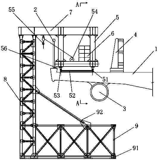
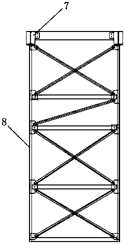
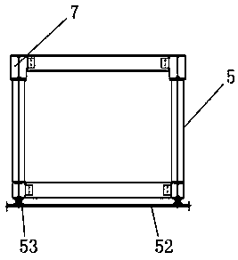
[0072] Such as Figure 1~Figure 4 As shown, 1. Bridge deck flange, 2. Railing, 3. Pipeline, 4. Water horse, 5. Driving, 51. Track, 52. Axle, 53. Moving wheel, 54. Hoist, 55. Hook, 56 .Wire rope, 6. Counterweight, 7. Beam, 8. Vertical truss, 9. Working platform, 91. Bottom plate, 92. Slanting bar.

[0073] Installation of mobile brackets and operation methods for pipelines on the underside of flanges of bridge decks in service, such as Figure 1~Figure 3 As shown, it is mainly used to quickly, conveniently, flexibly and firmly install the pipeline 3 section by section on the bottom surface of the deck flange 1 of the bridge in service.

[0074] Among them, the mobile support is installed along the longitudinal direction of the top surface of the flange 1 of the bridge deck, and the structure of each mobile support is exactly the same, according to f...


PUM


Abstract

The invention discloses an installation mobile support for a bridge floor flange bottom surface pipe of an in-service bridge and an operation method, and relates to the field of bridge construction. The structure of the support comprises a travelling crane, a beam, a vertical truss, a working platform, a hoist, a balancing weight and the like, the mobile support is arranged at two ends according to the length of a pipe which needs to be installed in a segment division mode respectively, and the two mobile supports move or are fixed along a track which is laid on the bridge floor flange top surface in the vertical direction so that the pipe can be lifted and fixedly arranged on the bridge floor flange bottom segment by segment, and the interval between two travelling cranes can be flexibly set according to the segment length of the pipe to be installed; meanwhile, the travelling crane of each mobile support is bound on the bottom of a handrail through a steel wire rope, the support can facilitate temporary fixing of the travelling crane and effectively prevent horizontal movement of the travelling crane along a bridge floor flange, and the improved installation mobile support for the bridge floor flange bottom surface pipe of the in-service bridge and the operation method have the advantages that the support is simple in structure, remarkable in working efficiency, low in cost, safe and reliable, and wide in application range, and can be more widely applied and popularized.

Description

technical field [0001] The invention relates to the field of bridge construction, in particular to a mobile support and an operation method for installing a pipeline on the flange bottom surface of a bridge deck in service. Background technique [0002] After the completion of large bridges across the strait or across large rivers, due to the needs of economic development or the original design defects and other reasons, it is necessary to add linear facilities such as pipelines on the bridges in service. These pipes are generally installed on the bottom of the flange of the bridge deck, divided into certain lengths and installed section by section. For example, it is difficult to install the existing inspection cranes at the bottom of the original bridge spanning structure, because the inspection cranes are single and the longitudinal length is limited, so they cannot be installed and fixed smoothly. A section of pipeline with a certain length; if a bridge inspection vehicl...

Claims


Application Information

Patent Timeline
IPC IPC(8): E01D21/00E01D19/12
CPCE01D19/125E01D21/00
Inventor 褚超敏叶文韬来佳雯林瀚蔡佰成胡潆之陈玲王欢黄杭凯戴贤斌邬丹峰祁俊戴鹏周一勤
Owner NINGBO COMM ENG CONSTR GRP
Why Eureka
Try Eureka