Fan, control unit for fan, and fan control method

A control unit and fan control technology, applied in pump control, non-variable-capacity pumps, pump devices, etc., can solve the problems of shortened service life, fan overload, poor heat dissipation effect, etc., and achieve the effect of increasing the demand for use

Inactive Publication Date: 2017-12-26
SUNONWEALTH ELECTRIC MACHINE IND
View PDF8 Cites 0 Cited by
  • Summary
  • Abstract
  • Description
  • Claims
  • Application Information

AI Technical Summary

Problems solved by technology

[0003] However, when either fan (such as figure 1 F5) abnormal, the abnormal fan F5 is not controlled, and the fan blades can rotate freely. Therefore, when the airflow generated by the other normally operating fans F1~F4 is large enough, the airflow will drive the abnormal The fan blades of the fan F5 rotate in reverse, causing the cold air to flow countercurrently before the heat exchange is complete, resulting in poor overall cooling effect
[0004] In order to solve the above problems, although the speed of the other normal fans F1~F4 can be further increased in order to increase the air flow to improve the heat dissipation effect, but the increase of the air flow will increase the speed of the abnormal fan F5, causing the flow of countercurrent air to increase. The increase, in addition to failing to effectively improve the heat dissipation effect, will also cause the normal fan to overload and shorten the service life

Method used


Image

  • Fan, control unit for fan, and fan control method
  • Fan, control unit for fan, and fan control method
  • Fan, control unit for fan, and fan control method

Examples


Embodiment Construction

[0047] In order to make the above-mentioned and other objects, features and advantages of the present invention more comprehensible, the preferred embodiments of the present invention are specifically cited below, together with the accompanying drawings, as follows:

[0048] The directional terms described throughout the present invention, such as front, back, left, right, upper (top), lower (bottom), inner, outer, side, etc., mainly refer to the directions of the drawings, and each directional term is only used The various embodiments of the present invention are used to assist in explaining and understanding the present invention, but are not intended to limit the present invention.

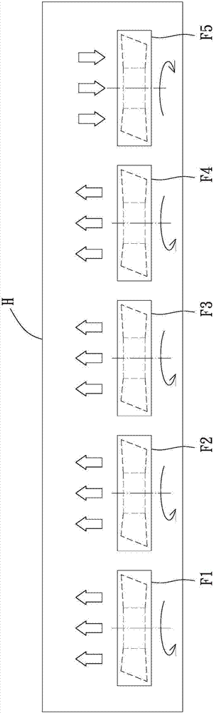
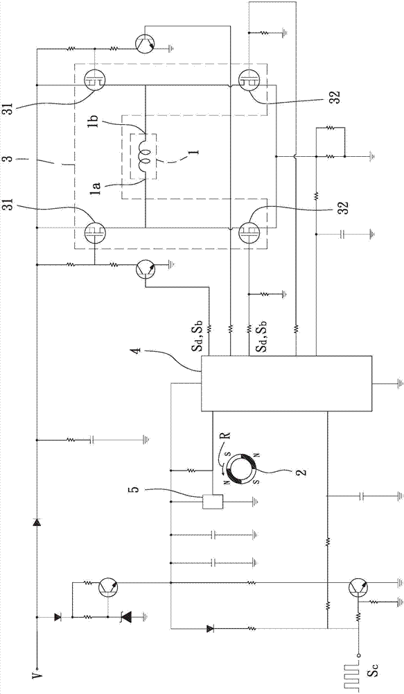
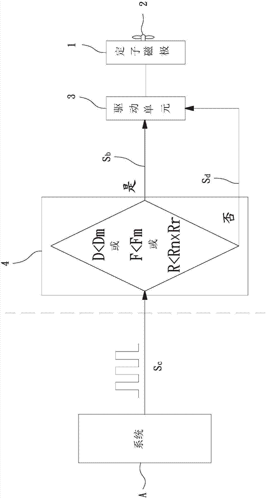
[0049] see figure 2 As shown, it is a schematic diagram of a fan circuit according to an embodiment of the present invention. Among them, please also refer to image 3 and Figure 4As shown, the fan embodiment may include a stator pole 1 , a fan wheel 2 , a drive unit 3 and a control unit 4...


PUM


Abstract

The present invention mainly provides a fan for solving the problem of poor cooling effect of the system due to abnormality of the fan. The fan may include a stator pole rotatably coupled to the fan wheel, and the stator pole is electrically connected with the driving unit. The driving The control unit is electrically connected to the driving unit. The control unit receives a speed control signal for driving the fan. The fan is driven by the stator poles. Wheel and controlling the rotation speed of the fan wheel. The control unit generates a braking signal according to the rotation speed or the speed control signal to brake the fan wheel. In this way, the above problems can be solved.

Description

technical field [0001] The invention relates to a fan, in particular to a fan which can prevent the fan wheel from rotating freely in response to abnormal conditions. Background technique [0002] The existing fan can drive the fan wheel to rotate to generate airflow to assist heat dissipation, such as figure 1 As shown, the existing heat dissipation system can be equipped with multiple fans F1~F5 in an electronic device H at the same time. The cold air from the outside takes away the heat inside the electronic device H, such as: waste heat generated by the operation of the central processing unit in the computer, etc., so as to improve the heat dissipation effect and prevent the electronic device from overheating and malfunctioning. [0003] However, when either fan (such as figure 1 F5) abnormal, the abnormal fan F5 is not controlled, and the fan blades can rotate freely. Therefore, when the airflow generated by the other normally operating fans F1~F4 is large enough, th...

Claims


Application Information

Patent Timeline
Patent Type & Authority Applications(China)
IPC IPC(8): F04D25/08F04D27/00
CPCF04D25/0606F04D25/08F04D27/007
Inventor 洪银树麦鸿钦
Owner SUNONWEALTH ELECTRIC MACHINE IND
Why Eureka
Try Eureka