Pressure feedback method and apparatus, computer device and storage medium

A technology of feedback device and computer program, which is applied in the direction of computer components, calculation, user/computer interaction input/output, etc., which can solve the problems that the user can effectively feel the vibration and the feedback effect of pressure is not good, and achieve the feedback effect Obvious, the effect of improving the feedback effect

Active Publication Date: 2017-12-26
INTERFACE TECH CHENGDU CO LTD +2
View PDF6 Cites 5 Cited by
  • Summary
  • Abstract
  • Description
  • Claims
  • Application Information

AI Technical Summary

Problems solved by technology

However, the duration of the vibration may be due to the fact that the user did not pay attention to the start time of the vibration

Method used


Image

  • Pressure feedback method and apparatus, computer device and storage medium
  • Pressure feedback method and apparatus, computer device and storage medium
  • Pressure feedback method and apparatus, computer device and storage medium

Examples


Example

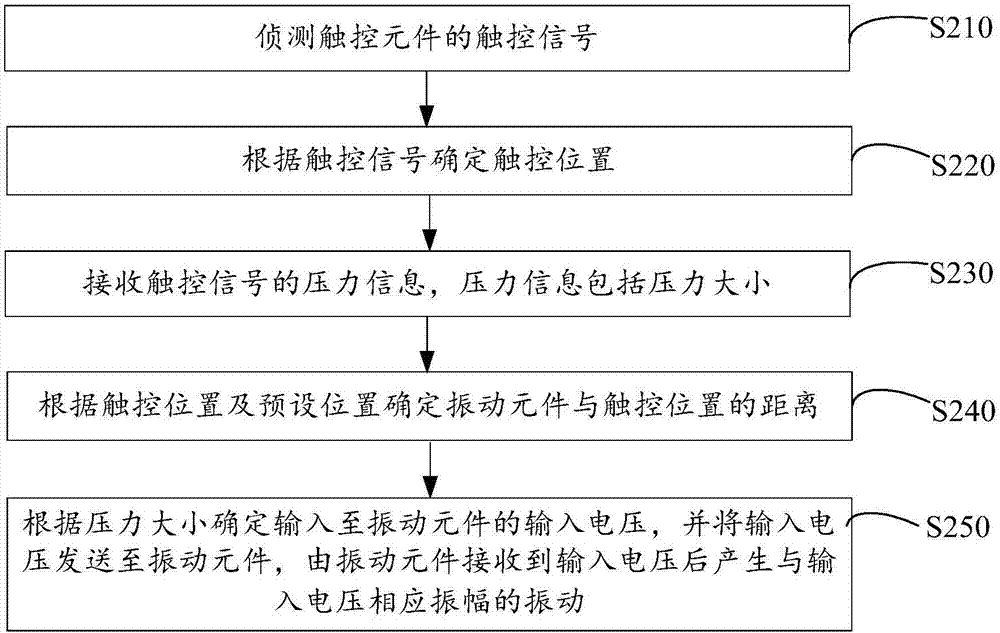
[0063] Example one, such as Picture 10 As shown, the position coordinates of the four vibrating elements, that is, the four preset position coordinates: P1 (X1, Y1) is (0,0), P2 (X2, Y2) is (0,800), P3 (X3, Y3) is (600,0) and P4 (X4, Y4) are (600,800); touch position P5 (X5, Y5) is (300,400); the maximum resolution includes the first dimension maximum resolution X and the second dimension maximum resolution Y , Where X=600 and Y=800. The distance between the touch position P5 and the preset position is the distance between the touch position and the vibration element. Among them, the calculation formula for the distance between the touch position and the preset position is Among them, i=1, 2, 3, 4. From the calculation formula, D 1 =500,D 2 = 500, D 3 = 500, D 4 =500, then b 1 = 50%, b 2 = 50%, b 3 = 50%, b 4 = 50%.

Example

[0064] Example two, such as Picture 11 As shown, the position coordinates of the four vibrating elements are four preset positions: P1 (X1, Y1) is (0,0), P2 (X2, Y2) is (0,800), P3 (X3, Y3) is ( 600,0) and P4 (X4, Y4) are (600,800); touch position P6 (X6, Y6) is (100,500); the maximum resolution includes the first dimension maximum resolution X and the second dimension maximum resolution Y, Among them, X=600 and Y=800. The distance between the touch position P6 and the preset position is the distance between the touch position and the vibration element. Among them, the calculation formula for the distance between the touch position and the preset position is Among them, i=1, 2, 3, 4. From the calculation formula, D 1 =509.90,D 2 = 316.23, D 3 =707.11, D 4 =583.10, then b 1 =49%, b 2 = 68%, b 3 = 29%, b 4 = 42%.

[0065] In one of the embodiments, the structural relationship of each element involved in the pressure feedback method, such as Picture 12 As shown, the touch eleme...


PUM


Abstract

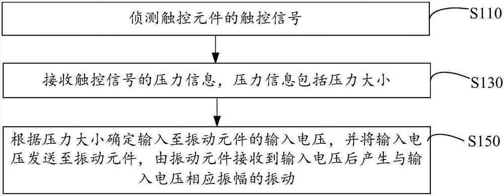
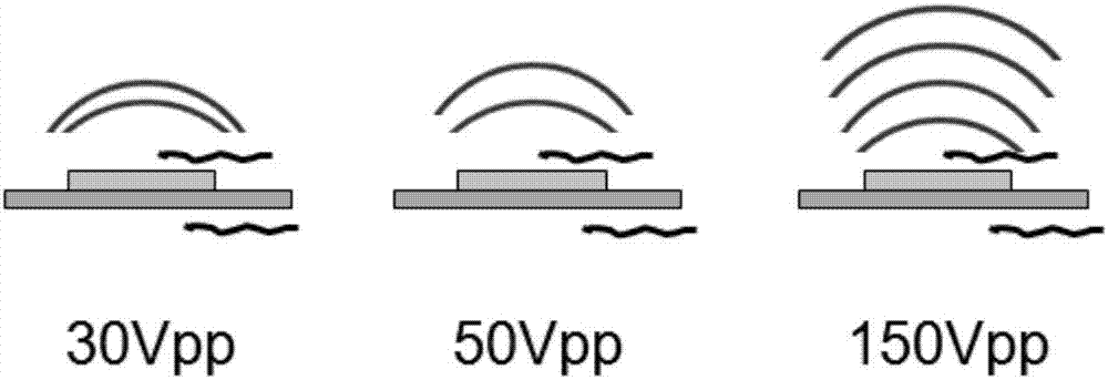
The invention provides a pressure feedback method and apparatus, a computer device and a storage medium. The method comprises the steps of detecting a touch signal of a touch element; receiving pressure information of the touch signal, wherein the pressure information comprises a pressure value; and according to the pressure value, determining an input voltage input to a vibration element, and sending the input voltage to the vibration element, thereby enabling the vibration element to generate a vibration with the amplitude corresponding to the input voltage after receiving the input voltage. The input voltage input to the vibration element can be determined according to the pressure value, so that the vibration element is controlled to generate the vibration with the amplitude corresponding to the input voltage; and therefore, a user can feel the vibration amplitude more effectively, namely, the pressure value feedback effect is remarkable, and the pressure value feedback effect is improved in comparison with that in a conventional mode.

Description

technical field [0001] The invention relates to the technical field of electronic equipment, in particular to a pressure feedback method and device, computer equipment and a storage medium. Background technique [0002] The pressure feedback of the electronic device refers to that when the user touches the electronic device, that is, when the electronic device is subjected to pressure, a vibration signal is fed back to inform the user that the electronic device is subjected to pressure. The electronic device may be a mobile phone. For example, the pressure sensor is set in the metal back cover of the mobile phone. When the finger presses the display screen, the display screen will be deformed, thereby changing the capacitance value between the sending end and the receiving end of the pressure sensor, and the pressure can be calculated from the capacitance value. The size, that is, changing the capacitance value changes the pressure. [0003] The traditional pressure feedba...

Claims


Application Information

Patent Timeline
IPC IPC(8): G06F3/01G06F3/0488
CPCG06F3/016G06F3/0488
Inventor 管益章廖致霖
Owner INTERFACE TECH CHENGDU CO LTD
Why Eureka
Try Eureka