Medical spring ring and conveying system comprising same

A technology of a coil and a spring unit, applied in the field of medical devices, can solve the problems of increasing the surgical risk of patients, the risk of easy kicking, and the poor flexibility of the unit connection position, so as to avoid prolonging the operation time, avoid aneurysm rupture, and improve the The effect of surgical safety

Pending Publication Date: 2022-03-29
MICROPORT NEUROTECH SHANGHAI
View PDF0 Cites 0 Cited by
  • Summary
  • Abstract
  • Description
  • Claims
  • Application Information

AI Technical Summary

Problems solved by technology

The main defect is that the one-piece coil product has poor connection flexibility between the units. During the filling process, the subsequent filled units continuously exert force in different directions on the filled unit, causing the position of the coil to change and flip in the aneurysm. Happening
Flipping will cause relative sliding between the product and the aneurysm, and friction will easily increase the risk of aneurysm rupture
[0005] The second defect is that the one-piece design results in a longer spring coil length, and the front-end units are continuously stacked, resulting in the final filling unit being tightened, resulting in an increase in the hardness of the rear-end spring coil, which is very prone to the risk of tube kicking
The kicking tube is the reaction force of the microcatheter during the filling process of the coil. The increase in product hardness will lead to an increase in the reaction force of the microcatheter, forcing the microcatheter to swing and move backward, and the aneurysm will fall. Reoperation needs to adjust the microcatheter , increasing the operating time will increase the patient's surgical risk
Therefore, the design of the one-piece spring coil has defects such as long length, poor flexibility at the unit connection position, easy flipping inside the tumor, and kicking the tube.

Method used


Image

  • Medical spring ring and conveying system comprising same
  • Medical spring ring and conveying system comprising same
  • Medical spring ring and conveying system comprising same

Examples


Embodiment 1

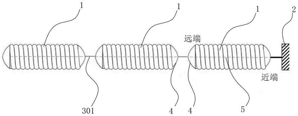
[0039] Please refer to figure 1 , a medical coil, the coil includes at least two first spring units 1, and the adjacent first spring units 1 are flexibly connected.

[0040] Further, please refer to figure 1 , the first spring unit 1 is preferably 2 to 10 segments, and the first spring unit 1 in the spring coil provided by this embodiment is most preferably 2 to 5 segments, and the adjacent first spring units 1 are flexibly connected in sequence from the beginning to the end . The first spring unit 1 includes, but is not limited to, a helical 2D primary structure or a 3D secondary structure or other spring structures.

[0041] Further, the above-mentioned flexible connection selects a polymer wire as the connecting wire 301, the proximal end and / or the distal end of the connecting wire 301 are extended and penetrated into the first spring unit 1, and the extended part of the first spring unit 1 penetrates to form an anti-decomposition The spinning thread 5 (that is, the ant...

Embodiment 2

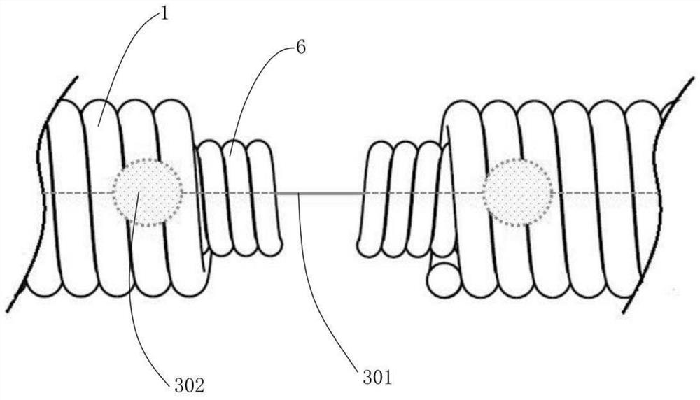
[0046] In the second embodiment, the first spring unit 1 and the connection wire 301 are the same as the first embodiment. The difference between the second embodiment and the first embodiment is that the medical spring coil is equipped with the second spring unit 6 and the fixing part 4 is eliminated. The following description The specific structure of the medical coil provided with the second spring unit 6:

[0047] Further, please refer to figure 2 , the connection wire 301 is connected to the proximal end and / or the distal end of the first spring unit 1 through the second spring unit 6 . Specifically, a part of the second spring unit 6 protrudes into the first spring unit 1. The second spring unit 6 uses a thin spring coil. The material of the second spring unit 6 includes but is not limited to One or more of platinum materials and stainless steel materials. The second spring unit 6 is connected to the first spring unit 1, specifically, the second spring unit 6 is coaxi...

Embodiment 3

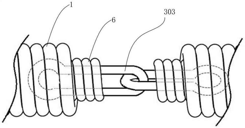
[0052] The medical spring coil described in Embodiment 3 and Embodiment 2 use the first spring unit 1 and the connecting wire 301 with the same structure, but the difference between the medical coil described in Embodiment 3 and Embodiment 2 is that the second spring unit 6 The structure is different, as follows:

[0053] Further, please refer to Figure 4 , the connection wire 301 is connected to the proximal end and / or the distal end of the first spring unit 1 through the second spring unit 6 . Specifically, the second spring unit 6 is coaxially nested and connected to the first spring unit 1, that is, the second spring unit 6 is an independent structure and is different from the first spring unit 1, but the medical coil described in the third embodiment The second spring unit 6 fixes the connecting wire 301 by reducing its diameter.

[0054] Specifically, when the first spring unit 1 and the second spring unit 6 are nested and connected, the diameter reduction refers to a...


PUM


Abstract

The invention relates to a medical spring ring which comprises at least two sections of first spring units, and the adjacent first spring units are flexibly connected. According to the medical spring ring, an integrated structure of the spring ring is changed into flexible connection of the multiple sections of first spring units, and the sections of first spring units are not directly connected, so that the sections of first spring units are not directly connected, and force transmission does not exist; interference between the two connected first spring units in the spring ring filling process can be avoided, and the intra-tumor overturning phenomenon generated by an integrated spring ring in an operation is avoided. Furthermore, the conditions of superposition and tail end tightening caused by traditional integrated structure filling cannot be caused by filling of all the independent first spring units, so that the tube kicking phenomenon is reduced, the product operation safety is improved, the risks of aneurysm rupture and operation time prolonging are avoided, the life safety of a patient is guaranteed, and the safety of the patient is improved. Good use feedback of doctors is obtained, and the product complaint rate is low.

Description

technical field [0001] The invention relates to the technical field of medical devices, in particular to a medical coil with multi-segment flexible connection and a delivery system comprising the coil. Background technique [0002] Intracranial aneurysm is a tumor-like protrusion formed by expansion or expansion of the arterial vessel wall due to cerebrovascular wall lesions or injuries. Once the aneurysm ruptures, it can easily cause intracranial subarachnoid hemorrhage, which has a high mortality rate and disability. Rate. The basic structure of the coils on the market is a medical device with a ball spring structure formed by alloy wires. The delivery device is used to sequentially deliver the coils to the position of the diseased aneurysm through a microcatheter, fill it into the aneurysm, change the blood flow in the tumor, and form an embolism. The therapeutic effect is achieved by closing the aneurysm to prevent further development of the aneurysm leading to rupture ...

Claims


Application Information

Patent Timeline
Patent Type & Authority Applications(China)
IPC IPC(8): A61B17/12
CPCA61B17/12022A61B17/12113A61B17/12145A61B2017/1205
Inventor 于凯李爱勤彭云飞李牧晨魏凌轩
Owner MICROPORT NEUROTECH SHANGHAI
Why Eureka
Try Eureka