Pneumatic piston actuating mechanism with clutch type hand-operating mechanism for sluice valve

A technology of pneumatic actuators and manual mechanisms, applied in engine components, valve operation/release devices, valve details, etc., can solve the problems of high labor intensity, high cost, long time, etc., to improve operation stability and reduce distance. , the effect of reducing the height

Active Publication Date: 2019-01-29
WUXI SCORE AUTOMATIC CONTROL EQUIP CO LTD
View PDF7 Cites 0 Cited by
  • Summary
  • Abstract
  • Description
  • Claims
  • Application Information

AI Technical Summary

Problems solved by technology

[0002] In large-scale oil refineries, chemical plants and storage tanks, many switch gate valves are used to cut off the medium in the pipeline. Because the cost of human resources is increasing year by year, and it takes a long time to switch a valve, the labor intensity is high and urgent. It is necessary to use automated devices instead of labor to improve work efficiency, and because such working conditions generally have high explosion-proof requirements, general electric actuators cannot meet their requirements, and electric actuators that meet their explosion-proof requirements are expensive. Therefore, the pneumatic actuator has become the first choice for the driving device, and in order to force the valve to switch under special circumstances, the pneumatic actuator needs to be equipped with a clutch type manual operating mechanism

Method used


Image

  • Pneumatic piston actuating mechanism with clutch type hand-operating mechanism for sluice valve
  • Pneumatic piston actuating mechanism with clutch type hand-operating mechanism for sluice valve
  • Pneumatic piston actuating mechanism with clutch type hand-operating mechanism for sluice valve

Examples


Embodiment Construction

[0022] Hereinafter, the present invention will be described in detail with reference to the accompanying drawings. It should be noted that, in the case of no conflict, the embodiments in the present application and the features in the embodiments can be combined with each other.

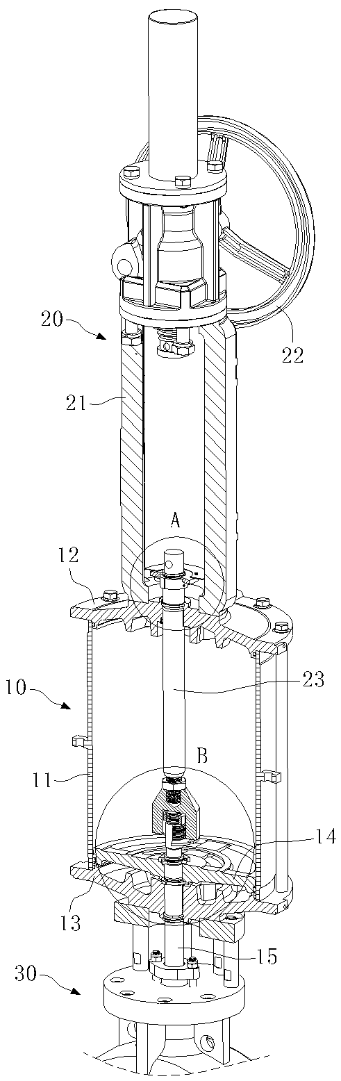
[0023] see figure 1 .

[0024] A pneumatic piston actuator with a clutch type manual mechanism for a gate valve of the present invention includes a pneumatic actuator 10 and a clutch type manual operation mechanism 20, and the pneumatic actuator 10 includes a cylinder body 11, an upper end cover 12, and a lower end cover 13. Piston 14 and piston rod 15. The clutch type manual operating mechanism 20 includes a bracket 21, a hand wheel 22, a screw nut transmission structure and a push rod 23; the bracket 21 is fixed on the top of the upper end cover 12, and the The upper end of the piston rod 15 passes through the piston 14, the lower end of the push rod 23 passes through the upper end cover 12 and i...


PUM


Abstract

The invention discloses a pneumatic piston actuating mechanism with a clutch type hand-operating mechanism for a sluice valve. The pneumatic piston actuating mechanism comprises a pneumatic actuatingmechanism and the clutch type hand-operating mechanism, wherein the pneumatic actuating mechanism comprises a cylinder body, an upper end cover, a lower end cover, a piston and a piston rod; the clutch type hand-operating mechanism comprises a support, a handwheel, a leadscrew nut transmission structure and a push rod; and the support is fixed at the top of the upper end cover, the upper end of the piston rod penetrates through the piston, the lower end of the push rod penetrates through the upper end cover to be connected to the upper end of the piston rod, the lower end of the piston rod penetrates through the lower end cover, and a valve rod of a valve is double as the piston rod. According to the pneumatic piston actuating mechanism disclosed by the invention, the distance between thepneumatic actuating mechanism and a valve closing member can be effectively reduced, so that the integral height of the valve is reduced; and the problem that axiality does not exist between the piston rod and the valve rod is solved, the additional abrasion brought by linearity reduction caused by the connection of rod parts is reduced, and the operation stability of the valve and the pneumatic actuating mechanism is improved.

Description

technical field [0001] The invention relates to the field of valves, in particular to a pneumatic piston actuator with a clutch type manual mechanism for a gate valve. Background technique [0002] In large-scale oil refineries, chemical plants and storage tanks, many switch gate valves are used to cut off the medium in the pipeline. Because the cost of human resources is increasing year by year, and it takes a long time to switch a valve, the labor intensity is high and urgent. It is necessary to use automated devices instead of labor to improve work efficiency, and because such working conditions generally have high explosion-proof requirements, general electric actuators cannot meet their requirements, and electric actuators that meet their explosion-proof requirements are expensive. , Therefore, the pneumatic actuator has become the first choice for the drive device, and in order to force the valve to switch under special circumstances, the pneumatic actuator needs to be...

Claims


Application Information

Patent Timeline
Patent Type & Authority Applications(China)
IPC IPC(8): F16K31/122F16K31/60F16K37/00F16K41/02
CPCF16K31/122F16K31/60F16K37/0016F16K41/02
Inventor 刘建新冯敏董成
Owner WUXI SCORE AUTOMATIC CONTROL EQUIP CO LTD
Why Eureka
Try Eureka