Modular closed bending machine back stop device

A closed type bending machine technology, applied in the field of bending machines, can solve the problems of loose and complicated installation, poor material blocking accuracy, and low installation efficiency, and achieve the effects of strong load impact resistance, strong bearing capacity, and stable installation

Inactive Publication Date: 2017-12-29
ANHUI JACO NC MACHINE MFG
View PDF2 Cites 5 Cited by
  • Summary
  • Abstract
  • Description
  • Claims
  • Application Information

AI Technical Summary

Problems solved by technology

[0009] The present invention provides a modular closed type bending machine back gauge device, the purpose of which is to solve the problems of loose and complicated installation of parts and components of the existing back gauge device, low integration, low installation efficiency and poor material gauge accuracy

Method used


Image

  • Modular closed bending machine back stop device
  • Modular closed bending machine back stop device
  • Modular closed bending machine back stop device

Examples


Embodiment 1

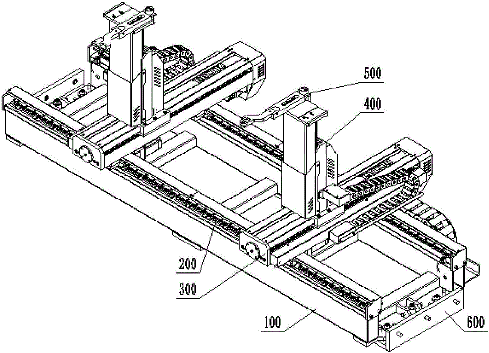
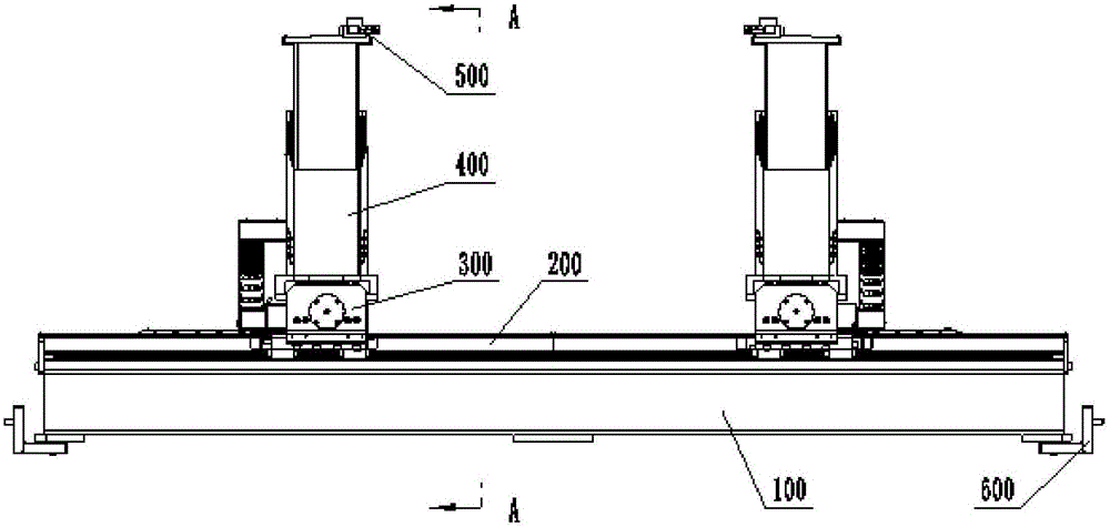
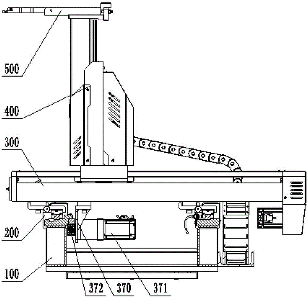
[0056] Such as figure 1 , figure 2 , image 3 As shown, this embodiment is a modular closed type bending machine back gauge, which is mainly composed of a pair of beams 100, an X-axis assembly 200, a Y-axis assembly 300, a Z-axis assembly 400, and a finger stop assembly 500. Among them, the X-axis assembly 200 is installed on the beam 100, the whole device is also installed on the bending machine through the beam 100, the Y-axis assembly 300 is installed on the X-axis assembly 200, and the X-axis assembly 200 is used to drive the Y-axis assembly 300 along the X-axis. The direction movement is the length direction of the bending machine; the Z-axis assembly 400 is installed on the Y-axis assembly 300, and the Y-axis assembly 300 is used to drive the movement of the Z-axis assembly 400 along the Y-axis direction, which is the width direction of the bending machine; The finger stop assembly 500 is installed on the Z axis assembly 400. The Z axis assembly 400 is used to drive the f...

Embodiment 2

[0068] This embodiment is an integrated and interoperable backgauge device for a bending machine. Its structure is basically the same as that of the first embodiment, except that the structure installed on the bending machine is optimized. It can be seen from Example 1 that the back gauge is installed by fixing the two ends of the beam 100 to the left and right wall panels of the bending machine. However, due to processing and installation errors, it will inevitably lead to the installation of the back gauge. There is a slight difference in the height of the two beams 100 in the vertical direction, and the two ends of the beam 100 will also be offset in the front and rear directions, which will cause the X-axis, Y-axis, and Z-axis to move greatly. The error caused by the inaccuracy of the stopper position, and this error cannot be eliminated by the adjustment of each axis motor, so the structure of the beam 100 installed on the bending machine is very important to the accuracy o...


PUM


Abstract

The invention discloses a modular closed type bending machine back gauge device, which belongs to the technical field of bending machines. It includes a pair of crossbeams, an X-axis assembly, a Y-axis assembly, a Z-axis assembly, and a finger assembly; the pair of crossbeams are arranged in parallel and at intervals, and each crossbeam is provided with an X-axis assembly; the Y-axis assembly is supported on On the X-axis assembly, the X-axis assembly is used to drive the Y-axis assembly to move along the X-axis direction; the Z-axis assembly is installed on the Y-axis assembly, and the Y-axis assembly is used to drive the Z-axis assembly to move along the Y-axis direction; the stopper The finger assembly is installed on the Z-axis assembly, and the Z-axis assembly is used to drive the finger assembly to move along the Z-axis. The rear stopper device of the present invention adopts a modular design, which is independent from the bending machine, and can be installed on the bending machine as a whole at one time, and can adjust the position of the stopper up and down, left and right, front and back, to meet various stoppers It has good versatility, interchangeability and strong impact resistance.

Description

Technical field [0001] The invention belongs to the technical field of bending machines, and more specifically, relates to a modular closed type bending machine back gauge. Background technique [0002] The bending machine is a machine that can bend thin plates. It includes a bracket, a working table, a clamping plate and a back gauge. The working table is placed on the bracket. The working table is composed of a base and a pressure plate. The tight plate is connected. Bending machine products are widely used in electromechanical, sheet metal, light industry, aviation, shipbuilding, instrumentation, electrical appliances, stainless steel products, steel structure construction, metallurgy and other industries. They are used to bend various steel plates, stainless steel, copper plates, aluminum plates and non-metals. Material plate, it can fold the product into V-shaped, arc-shaped, round or right-angled shape, etc., and can also be designed and processed into special-shaped molds...

Claims


Application Information

Patent Timeline
Patent Type & Authority Applications(China)
IPC IPC(8): B21D5/00B21D43/00
CPCB21D5/002B21D43/003
Inventor 费文彪李忠华
Owner ANHUI JACO NC MACHINE MFG
Why Eureka
Try Eureka