Polishing device for wind power generation blade

A technology for wind power generation and blades, which is applied in grinding/polishing safety devices, grinding machines, grinding/polishing equipment, etc., and can solve the problems of complicated operation, inconvenient use and poor grinding effect.

Inactive Publication Date: 2017-12-29
王臻
View PDF9 Cites 7 Cited by
  • Summary
  • Abstract
  • Description
  • Claims
  • Application Information

AI Technical Summary

Problems solved by technology

[0005] In order to overcome the disadvantages of complicated operation, inconvenient use and poor grinding effect in the existing grinding device, the technical problem to be solved by the invention is to provide a grinding device for wind power generation blades with simple operation, convenient use and good grinding effect

Method used


Image

  • Polishing device for wind power generation blade
  • Polishing device for wind power generation blade
  • Polishing device for wind power generation blade

Examples


Embodiment 1

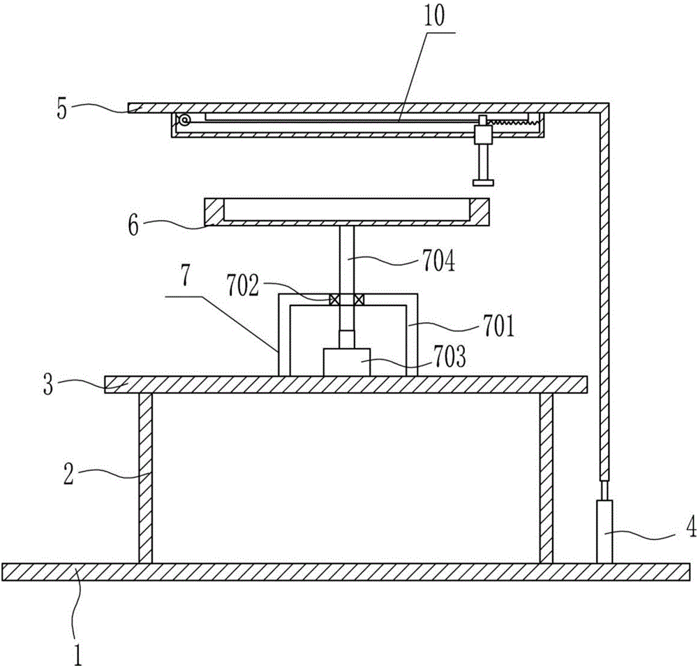
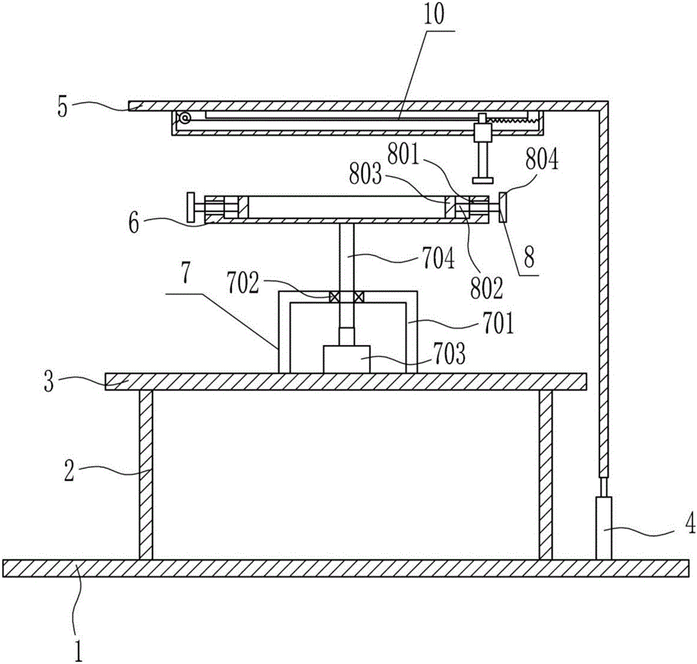
[0037] A grinding device for blades of wind power generation, such as Figure 1-7 As shown, it includes a bottom plate 1, a strut 2, a horizontal plate 3, a cylinder 4, a 7-shaped plate 5, a U-shaped placement plate 6, a rotating device 7, and a left and right moving mechanism 10. The top of the bottom plate 1 is welded with a strut 2, and the strut 2 The top is welded with a horizontal plate 3, and the top of the horizontal plate 3 is equipped with a rotating device 7. The rotating part on the rotating device 7 is connected with a U-shaped placement plate 6, and the right side of the top of the bottom plate 1 is connected with a cylinder 4 by bolts, and the telescopic rod of the cylinder 4 Be connected with 7-type plate 5, and left-right movement mechanism 10 is installed on the top of 7-type plate 5, and the grinding part on the left-right movement mechanism 10 is positioned at the top of U-shaped placement plate 6.

Embodiment 2

[0039] A grinding device for blades of wind power generation, such as Figure 1-7 As shown, it includes a bottom plate 1, a strut 2, a horizontal plate 3, a cylinder 4, a 7-shaped plate 5, a U-shaped placement plate 6, a rotating device 7, and a left and right moving mechanism 10. The top of the bottom plate 1 is welded with a strut 2, and the strut 2 The top is welded with a horizontal plate 3, and the top of the horizontal plate 3 is equipped with a rotating device 7. The rotating part on the rotating device 7 is connected with a U-shaped placement plate 6, and the right side of the top of the bottom plate 1 is connected with a cylinder 4 by bolts, and the telescopic rod of the cylinder 4 Be connected with 7-type plate 5, and left-right movement mechanism 10 is installed on the top of 7-type plate 5, and the grinding part on the left-right movement mechanism 10 is positioned at the top of U-shaped placement plate 6.

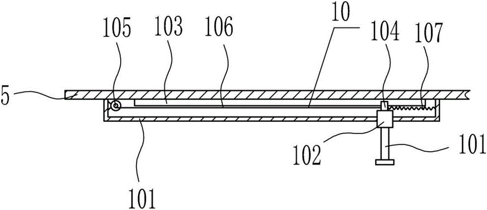
[0040] The left and right moving mechanism 10 includes a ...

Embodiment 3

[0042] A grinding device for blades of wind power generation, such as Figure 1-7 As shown, it includes a bottom plate 1, a strut 2, a horizontal plate 3, a cylinder 4, a 7-shaped plate 5, a U-shaped placement plate 6, a rotating device 7, and a left and right moving mechanism 10. The top of the bottom plate 1 is welded with a strut 2, and the strut 2 The top is welded with a horizontal plate 3, and the top of the horizontal plate 3 is equipped with a rotating device 7. The rotating part on the rotating device 7 is connected with a U-shaped placement plate 6, and the right side of the top of the bottom plate 1 is connected with a cylinder 4 by bolts, and the telescopic rod of the cylinder 4 Be connected with 7-type plate 5, and left-right movement mechanism 10 is installed on the top of 7-type plate 5, and the grinding part on the left-right movement mechanism 10 is positioned at the top of U-shaped placement plate 6.

[0043] The left and right moving mechanism 10 includes a ...


PUM


Abstract

The invention relates to polishing devices, in particular to a polishing device for a wind power generation blade. The polishing device for the wind power generation blade is easy to operate, convenient to use and good in polishing effect and comprises a bottom plate, supporting rods, a transverse plate, an air cylinder, a 7-shaped plate, a U-shaped storage plate and the like. The supporting rods are welded to the top of the bottom plate. The transverse plate is welded to the tops of the supporting rods. A rotating device is mounted on the top of the transverse plate. A rotating part on the rotating device is connected with the U-shaped storage plate. The right side of the top of the bottom plate is connected with the air cylinder through a bolt. A telescopic rod of the air cylinder is connected with the 7-shaped plate. The generation blade is polished through a polishing part on a horizontal moving device, chips are swept through a sweeping device, and accordingly the effects of good polishing effect, easy operation and convenient use are achieved.

Description

technical field [0001] The invention relates to a grinding device, in particular to a grinding device for wind power generation blades. Background technique [0002] The design of blades in wind turbines directly affects the conversion efficiency of wind energy and its annual power generation, which is an important part of wind energy utilization. [0003] The existing grinding device has the disadvantages of complicated operation, inconvenient use, and poor grinding effect. Therefore, it is urgent to develop a grinding device for wind power generation blades with simple operation, convenient use, and good grinding effect. Contents of the invention [0004] (1) Technical problems to be solved [0005] In order to overcome the disadvantages of complicated operation, inconvenient use and poor grinding effect in the existing grinding device, the technical problem to be solved by the invention is to provide a grinding device for wind power generation blades with simple operat...

Claims


Application Information

Patent Timeline
Patent Type & Authority Applications(China)
IPC IPC(8): B24B19/14B24B55/00
CPCB24B19/14B24B55/00
Inventor 王臻雷冲李冰
Owner 王臻
Why Eureka
Try Eureka