
Intelligent textile winding equipment

A winding equipment and textile technology, applied in the field of intelligent textile winding equipment, can solve the problems of inconvenient disassembly and installation, inability to adjust and install a bobbin, low winding efficiency, etc., so as to improve the disassembly and assembly speed and realize automatic reset and installation. work, improve work efficiency

Inactive Publication Date: 2017-12-29
CIXI KUANGYAN YINGYING BAMBOO PROD FACTORY GENERAL PARTNERSHIP
View PDF6 Cites 2 Cited by
  • Summary
  • Abstract
  • Description
  • Claims
  • Application Information

AI Technical Summary

Problems solved by technology

[0002] At present, the textile industry is developing faster and faster. Textile winding machines play an indispensable role in the textile industry. Traditional hand-operated textile winding machines are slow in speed and low in winding efficiency and cannot meet the current production needs. Automatic winding machines are gradually adopted The winding of the textile winding machine can improve the winding efficiency and reduce the confusion of the coils. However, due to the relatively troublesome operation of the current textile winding machine, and the size of the fixed winding drum on the textile winding machine is limited, It is not possible to adjust and install winding bobbins of different sizes and specifications according to needs, and some textile winding machines are integrally formed, which is not easy to disassemble and install
These have undoubtedly affected the work of the textile winding machine and brought inconvenience to the user.

Method used


Image

  • Intelligent textile winding equipment
  • Intelligent textile winding equipment
  • Intelligent textile winding equipment

Examples


Embodiment Construction

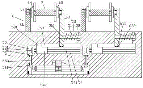
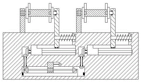
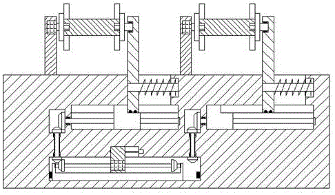
[0027] Such as Figure 1-Figure 8 As shown, an intelligent textile winding device of the present invention includes a frame 5 and a winding assembly 6 installed on the top end surface of the frame 5 and symmetrically arranged left and right. Each of the winding assemblies 6 includes a The support column 61 on the side, the adjustment column 63 arranged on the right side, and the bobbin 7 arranged between the support column 61 and the adjustment column 63, the left and right sides of the frame 5 are arranged symmetrically. Guide cavities 54, the top of each of the guide cavities 54 is connected with a through groove 53 extending along the left and right sides of the top of the guide cavity 54, and the top of the extension section on the right side of each of the through grooves 53 is connected with a Guide groove 51, the first sliding block 542 is connected with sliding fit in the described guiding cavity 54, the left side of the top of the first sliding block 542 is provided w...


PUM


Abstract

The invention discloses intelligent textile winding equipment comprising a rack and winding assemblies mounted on the end face of the top of the rack and arranged in a bilateral-symmetry mode. Each winding assembly comprises a supporting column arranged on the left side, an adjusting column arranged on the right side and a bobbin arranged between the supporting column and the adjusting column. Guide cavities extending leftwards and rightwards are formed in the rack in a bilateral-symmetry mode. A through groove is formed in the top of each guide cavity in a communicating mode, wherein the through groove extends along the left and right sides of the top of the guide cavity. A guide groove is formed in the top of the right-side extending section of each through groove in a communicating mode. First sliding blocks are connected in the guide cavities in a slide fit mode. Convex blocks extending into the through grooves are arranged on the left sides of the tops of the first sliding blocks. First thread rods extending leftwards and rightwards are connected into the first sliding blocks in a threaded fit mode. A transmission cavity is formed in the position, on the left side of each guide cavity, in the rack. The structure of the intelligent textile winding equipment is simple, intelligent control can be achieved, safety is improved, the mounting speed is increased, the equipment investment is reduced, and the manufacturing cost and the maintenance cost are lowered.

Description

technical field [0001] The invention relates to the technical field of textile processing, and relates to an intelligent textile winding device. Background technique [0002] At present, the textile industry is developing faster and faster. Textile winding machines play an indispensable role in the textile industry. Traditional hand-operated textile winding machines are slow in speed and low in winding efficiency and cannot meet the current production needs. Automatic winding machines are gradually adopted The winding of the textile winding machine can improve the winding efficiency and reduce the confusion of the coils. However, due to the relatively troublesome operation of the current textile winding machine, and the size of the fixed winding drum on the textile winding machine is limited, It is impossible to adjust and install winding bobbins of different sizes and specifications according to needs, and some textile winding machines are integrally formed, which is not ea...

Claims


Application Information

Patent Timeline
Patent Type & Authority Applications(China)
IPC IPC(8): B65H54/20B65H54/44B65H54/553B65H54/74
CPCB65H54/20B65H54/44B65H54/553B65H54/74B65H2701/31
Inventor 吴康康
Owner CIXI KUANGYAN YINGYING BAMBOO PROD FACTORY GENERAL PARTNERSHIP
Learn More