
Adjustable-type end beam assembly for bridge crane

A bridge crane, adjustable technology, applied in the direction of crane, traveling mechanism, load hanging element, etc., to achieve the effect of facilitating operation, reducing the wheel detachment from the guide rail, and reducing the loss

Inactive Publication Date: 2017-12-29
ANHU WUHU CHANGJIANG JACK UP EQUIP CO LTD
View PDF6 Cites 1 Cited by
  • Summary
  • Abstract
  • Description
  • Claims
  • Application Information

AI Technical Summary

Problems solved by technology

[0005] In order to overcome the shortcomings of the existing technical solutions, the present invention provides an adjustable end beam assembly for bridge cranes, which not only solves the use problems caused by the traditional fixed end beam assembly, but also greatly increases the usability of the end beam assembly , increase the construction efficiency, provide greater convenience for construction, reduce the friction between the end beam assembly and the guide rail, and facilitate the change of the relative position between the main beam and the end beam, which can effectively solve the problems raised by the background technology

Method used


Image

  • Adjustable-type end beam assembly for bridge crane
  • Adjustable-type end beam assembly for bridge crane
  • Adjustable-type end beam assembly for bridge crane

Examples


Embodiment

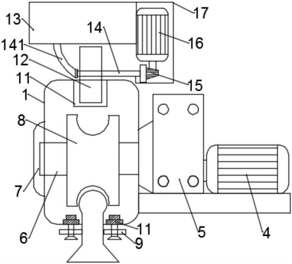
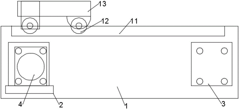
[0022] Such as figure 1 As shown, the present invention provides an adjustable end beam assembly of a bridge crane, including an end beam main frame 1, a driving wheel assembly 2 and a driven wheel assembly 3, and the driving wheel assembly 2 and the driven wheel assembly 3 are installed on the end beam assembly respectively. The two ends of the beam main frame 1, and the drive motor 4 is installed on the outer bottom plate of the driving wheel assembly 2, and the drive motor 4 is connected with the driving shaft 6 through the reducer 5, wherein one end of the driving shaft 6 is connected to the bearing The cover plate 7 is connected, and the other end of the driving shaft 6 is connected with the reducer 5, and the drive motor 4 will drive the driving shaft 6 to rotate evenly through the reducer 5, so that the driving shaft 6 drives the driving wheel 8 to rotate, and the The driving shaft 6 is fixedly installed inside the end beam main frame 1 through the bearing sleeve plate ...


PUM


Abstract

The invention discloses an adjustable-type end beam assembly for a bridge crane. The adjustable-type end beam assembly comprises an end beam body frame, a driving wheel assembly and a driven wheel assembly. The driving wheel assembly and the driven wheel assembly are installed at the two ends of the end beam body frame correspondingly, and a driving motor is installed on an outer side base plate of the driving wheel assembly. The driving motor is connected with a driving spindle through a speed reducer. The driving spindle is fixedly installed inside the end beam body frame through a bearing sleeve plate and is further sleeved with a driving wheel. A driven wheel is installed inside the driven wheel assembly. Limiting rolling wheels are installed below the driving wheel and the driven wheel. An adjusting sliding groove is formed above the driving wheel and the driven wheel. The limiting rolling wheels are fixedly mounted onto a lower side plate of the end beam body frame through corresponding support rods. The adjusting sliding groove is connected with a main beam pedestal plate through an adjusting wheel. A rotating shaft of the adjusting wheel is connected with an adjusting motor through a worm and gear, and the relative position between a main beam and an end beam can be adjusted.

Description

technical field [0001] The invention relates to the technical field of bridge cranes, in particular to an adjustable end beam assembly of a bridge crane. Background technique [0002] In mechanical equipment, cranes have a wide range of applications, and are widely used in factory workshops, engineering construction, logistics industries, etc. In many engineering workshops, cranes are indispensable equipment, and end beams are bridge cranes. It is an important part, but in the prior art, most of the end beam assemblies used in bridge cranes are traditional fixed end beam assemblies, which have the following deficiencies: [0003] (1) In the traditional fixed end beam assembly, the wheel is prone to tilt and offset when moving back and forth relative to the guide rail. At this time, the wheel will bear the extrusion of the side, which will cause serious wear and shorten the service life of the end beam assembly , and when the situation is serious, it is easy for the wheel to...

Claims


Application Information

Patent Timeline
Patent Type & Authority Applications(China)
IPC IPC(8): B66C9/14
CPCB66C9/14B66C2700/018
Inventor 焦来文
Owner ANHU WUHU CHANGJIANG JACK UP EQUIP CO LTD
Learn More