
Double-frequency relativistic backward-wave oscillator capable of directly outputting TE11-mode electromagnetic waves

A TE11, electromagnetic wave technology, applied in the field of high-power microwave devices, can solve problems such as cost increase, large size, and complex structure

Active Publication Date: 2017-12-29
UNIV OF ELECTRONICS SCI & TECH OF CHINA
View PDF7 Cites 8 Cited by
  • Summary
  • Abstract
  • Description
  • Claims
  • Application Information

AI Technical Summary

Problems solved by technology

[0004] In order to solve the above technical problems, the present invention provides a 11 Dual-frequency relativistic return wave oscillator for mode electromagnetic waves to achieve dual-frequency TE output directly without additional mode converters 11 The electromagnetic wave of the mode solves the TM generated by the relativistic return wave oscillator in the current application with the purpose of having the beat wave effect, simplifying the structure and reducing the cost. 01 Mode electromagnetic wave loading mode converter and other devices for TM 01 to TE 11 mode switching, usually relativistic return wave oscillators produce reverse TM 01 After the mode electromagnetic wave, it is necessary to reflect the electromagnetic wave through the reflection neck or the reflection working cavity set in front of the slow wave structure, so that the electromagnetic wave is radiated along the direction of the electron injection, because in practical applications, more TE 11 Mode of electromagnetic waves, so a mode converter must be used for mode conversion, resulting in a relatively complex and bulky structure, and a corresponding increase in cost

Method used


Image

  • Double-frequency relativistic backward-wave oscillator capable of directly outputting TE11-mode electromagnetic waves

Examples


Embodiment Construction

[0017] The present invention will be described in further detail below in conjunction with specific embodiments. The purpose of the following words is to illustrate the present invention, rather than limit the protection scope of the present invention.

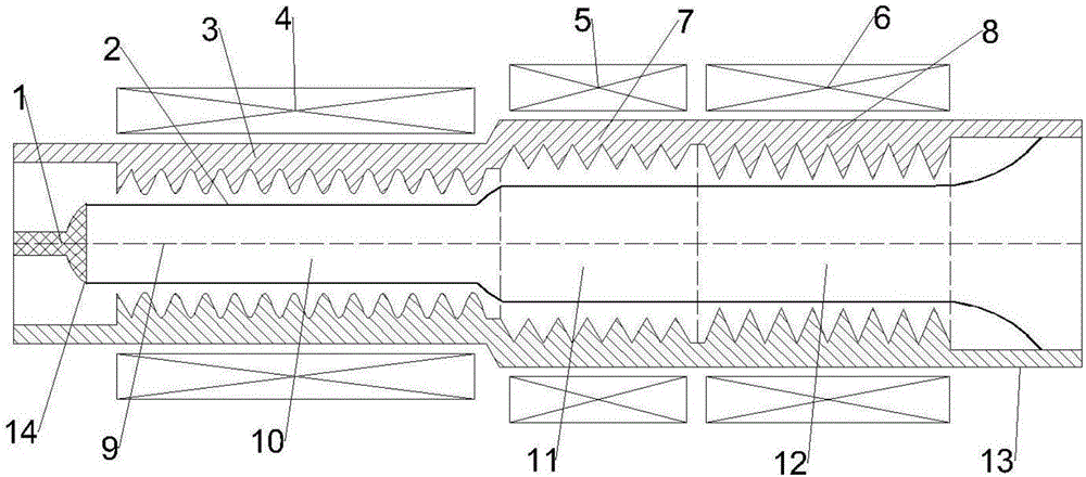
[0018] Such as figure 1 As shown, the present invention can be implemented in the following manner, one can directly output TE 11 The double-frequency relativistic return wave oscillator of the mode electromagnetic wave comprises a Bragg reflector 3 and a first slow-wave structure 7 coaxially connected to the end of the Bragg reflector 3, and the end of the first slow-wave structure 7 is coaxially connected with a second The slow wave structure 8, and the end of the second slow wave structure 8 is provided with an electron collector 13, and finally the electron beam 2 falls on the electron collector 13 after completing the injection wave interaction; the inner coaxial of the beginning of the Bragg reflector 3 An electron inje...


PUM


Abstract

The invention relates to the technical field of high-power microwave devices, and discloses a double-frequency relativistic backward-wave oscillator capable of directly outputting TE11-mode electromagnetic waves. The oscillator comprises a Bragg reflector, a first slow wave structure and a second slow wave structure, wherein the Bragg reflector, the first slow wave structure and the second slow wave structure are sequentially set in a coaxial manner. The interior of the Bragg reflector is sequentially provided with an electron beam emission gun and a reflection work cavity. The first slow wave structure comprises a slow wave structure employing a periodic ripple design, and the interior of the slow wave structure is provided with a slow wave structure beam-wave interaction cavity. The second slow wave structure comprises a slow wave structure employing a periodic ripple design, and the interior of the slow wave structure is provided with a slow wave structure beam-wave interaction cavity. According to the invention, an electron beam sequentially passes through two coaxial slow wave structures, and performs the beam-wave interaction with the slow wave structures to generate a double-frequency TE11-mode electromagnetic wave traveling in an opposite direction. The double-frequency TE11-mode electromagnetic wave traveling in the opposite direction is converted into a TE11-mode electromagnetic wave propagating forwards through the Bragg reflector, and the electromagnetic wave with the beat effect is outputted at a radiation end.

Description

technical field [0001] The invention relates to the technical field of high-power microwave devices, in particular to a device capable of directly outputting TE 11 A dual-frequency relativistic return-wave oscillator for mode electromagnetic waves. Background technique [0002] Since the 1970s, the research of high power microwave in high power, high efficiency, long pulse, repetition frequency operation, frequency locking and phase locking has made great progress. In addition, there are also some other research and development trends in high-power microwave sources, such as dual-frequency and multi-frequency high-power microwave source technology, that is, a single microwave source generates two or more frequency of microwaves. The emergence of dual-frequency and multi-frequency high-power microwave sources breaks the conventional practice of single-frequency HPM sources simply pursuing high power, high efficiency, long pulse and repetition frequency operation, and the be...

Claims


Application Information

Patent Timeline
IPC IPC(8): H01J25/46H01J23/09H01J23/27
CPCH01J23/09H01J23/27H01J25/46
Inventor 李海龙叶齐铖王茂琰王彬殷勇蒙林
Owner UNIV OF ELECTRONICS SCI & TECH OF CHINA
Learn More