Channel selector for a radio frequency receiver

A technology for radio frequency receivers and selectors, applied in the field of selectors, can solve problems such as interruption and damaged audio display

Active Publication Date: 2018-01-02
CONTINENTAL AUTOMOTIVE FRANCE +1
View PDF10 Cites 0 Cited by
  • Summary
  • Abstract
  • Description
  • Claims
  • Application Information

AI Technical Summary

Problems solved by technology

The smaller the minimum value MinBP0, the more likely to continue to select channel C 0 (regardless of the large interference level B), but the channel C so chosen 0 more prone to produce impaired audio presentation
If the value MinBP0 is larger, the channel C 0 will produce a less impaired audio presentation on average, but for lower interference levels B the selection will break

Method used


Image

  • Channel selector for a radio frequency receiver
  • Channel selector for a radio frequency receiver
  • Channel selector for a radio frequency receiver

Examples


Embodiment Construction

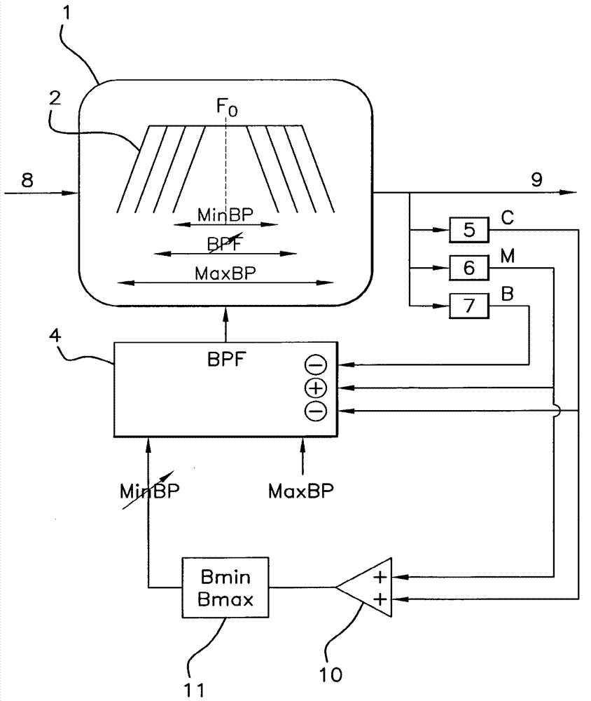
[0037] Such as Figure 6 shown, with Figure 5 Compared to the channel C of the FM radio frequency receiver according to the present invention 0 The selector 1 includes a bandpass filter 2 or a selection filter 2 .

[0038] The selector 1 receives an initial signal 8 as an input, and the initial signal 8 may be a fundamental frequency signal directly from an antenna or a signal whose frequency has been reduced beforehand, such as an intermediate frequency signal. Selector 1 produces a homologous source according to the band BPF but is reduced in frequency to only channel C 0 (for example, by selecting filter 2 to filter) the signal 9 as output. Signal 9 can be processed by a demodulator.

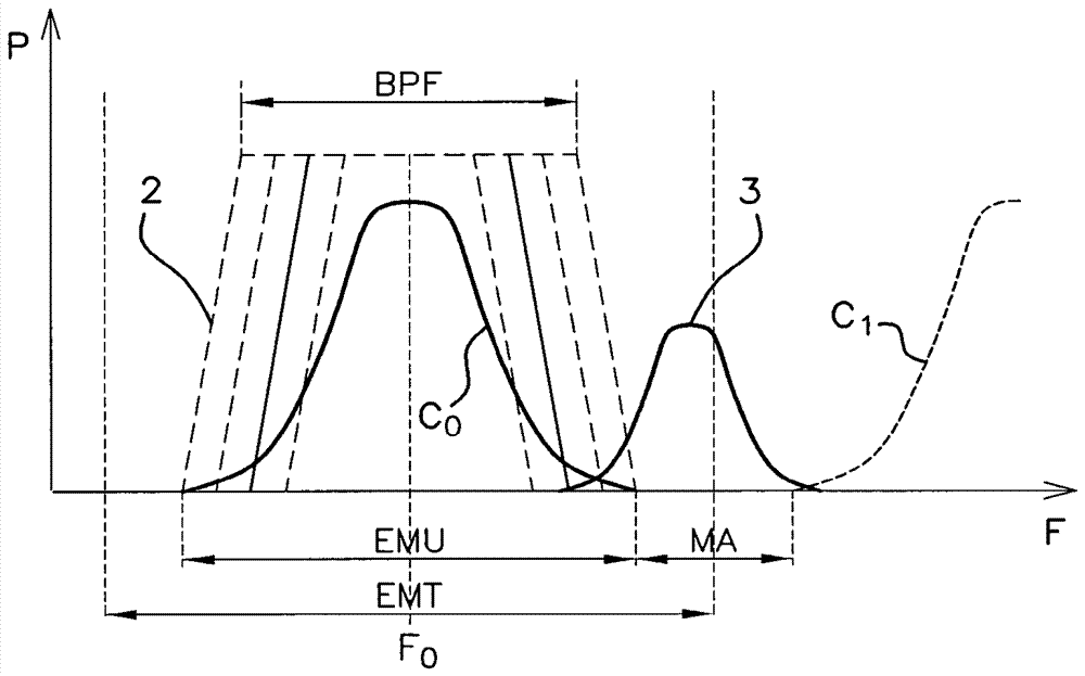
[0039] The bandpass filter 2 is characterized by the frequency band BPF of the filter, which is based on the channel C to be selected 0 The characteristic center frequency F 0 Centered and has a variable width. According to this variability, usually according to the channel C 0 The c...


PUM


Abstract

A channel selector (C0) for a frequency modulation radio frequency receiver, comprising a band-pass filter (2), of which the frequency band (BPF) is centred on the central frequency (F0) of the channel to be selected, and has a width that is automatically variable between a minimum value (MinBP) and a maximum value (MaxBP), the minimum value being determined dynamically proportional to a weightedsum of the field level (C) and the modulation level (M) of the channel, according to a formula MinBW = k1 x C + k2 x M, in which MinBW is the minimum value, C the field level, k1 the weight associatedwith the field level, M the modulation level, and k2 the weight associated with the modulation level, characterised in that the weight (k1) associated with the field level is less than the weight (k2) associated with the modulation level, preferably in a ratio of 1:3.

Description

technical field [0001] The present invention relates to the field of radio frequency reception, and more particularly to a selector for selecting a channel deployed in an FM radio frequency receiver. Background technique [0002] In a known manner, a frequency-modulated radio frequency signal uses a channel-specific center frequency and encodes its information by varying the frequency around said center frequency. [0003] In many countries, FM frequency plans deploy center frequencies every 200 kHz. Such as figure 1 shown, which shows the power P according to the frequency F, therefore, the channel C 0 have to be included in the ratio center frequency F 0 100kHz lower and than the center frequency F 0 Total modulation range EMT between up to 100kHz. In practice, to avoid the risk of overlap, and to facilitate channel extraction or selection from the complete and possibly multiple-channel received signal, the modulation range is limited to the effective (utile) modulati...

Claims


Application Information

Patent Timeline
Patent Type & Authority Applications(China)
IPC IPC(8): H03G5/24H03D3/00H04L27/14
CPCH03D3/005H04L27/14H03G5/24H04L27/10
Inventor L.泰里
Owner CONTINENTAL AUTOMOTIVE FRANCE
Why Eureka
Try Eureka