Turbocharger control valve for retaining back pressure and maintaining boost pressure

a control valve and turbocharger technology, applied in the direction of electric control, machines/engines, mechanical equipment, etc., can solve the problems of spools being further away from the extended feedback cap, and reducing the boost pressure. , to achieve the effect of increasing the boost pressure of the engine, improving the performance of the turbocharger, and increasing the boost pressur

Active Publication Date: 2022-05-03
EZRA EYAL
View PDF12 Cites 0 Cited by
  • Summary
  • Abstract
  • Description
  • Claims
  • Application Information

AI Technical Summary

Benefits of technology

[0008]An aspect of an example embodiment in the present disclosure is to provide a turbocharger control valve which improves turbocharger performance by maintaining exhaust pressure. The turbocharger harnesses exhaust gas from the engine to increase boost pressure to the engine using a compressor. The compressor is powered by a turbine assembly having a turbine wheel, a variable geometry assembly with a variable inlet adapted to move between a closed position and an open position, and a hydraulic actuation assembly having a piston which actuates the variable geometry assembly to move the variable inlet between the closed and open positions. The variable inlet closes to increase the velocity of the exhaust gas flowing through the turbine assembly to rotate the turbine wheel, allowing the turbocharger to deliver greater boost pressure at low engine speeds, and opens as exhaust gas pressure increases at high engine speeds, pot

Problems solved by technology

The variable inlet closes to increase the velocity of the exhaust gas flowing through the turbine assembly to rotate the turbine wheel, allowing the turbocharger to deliver greater boost pressure at low engine speeds, and opens as exhaust gas pressure increases at high engine speeds, potentially causing a premature decrease in boost pressure if engine speed decreases w

Method used


Image

  • Turbocharger control valve for retaining back pressure and maintaining boost pressure
  • Turbocharger control valve for retaining back pressure and maintaining boost pressure
  • Turbocharger control valve for retaining back pressure and maintaining boost pressure

Examples


Embodiment Construction

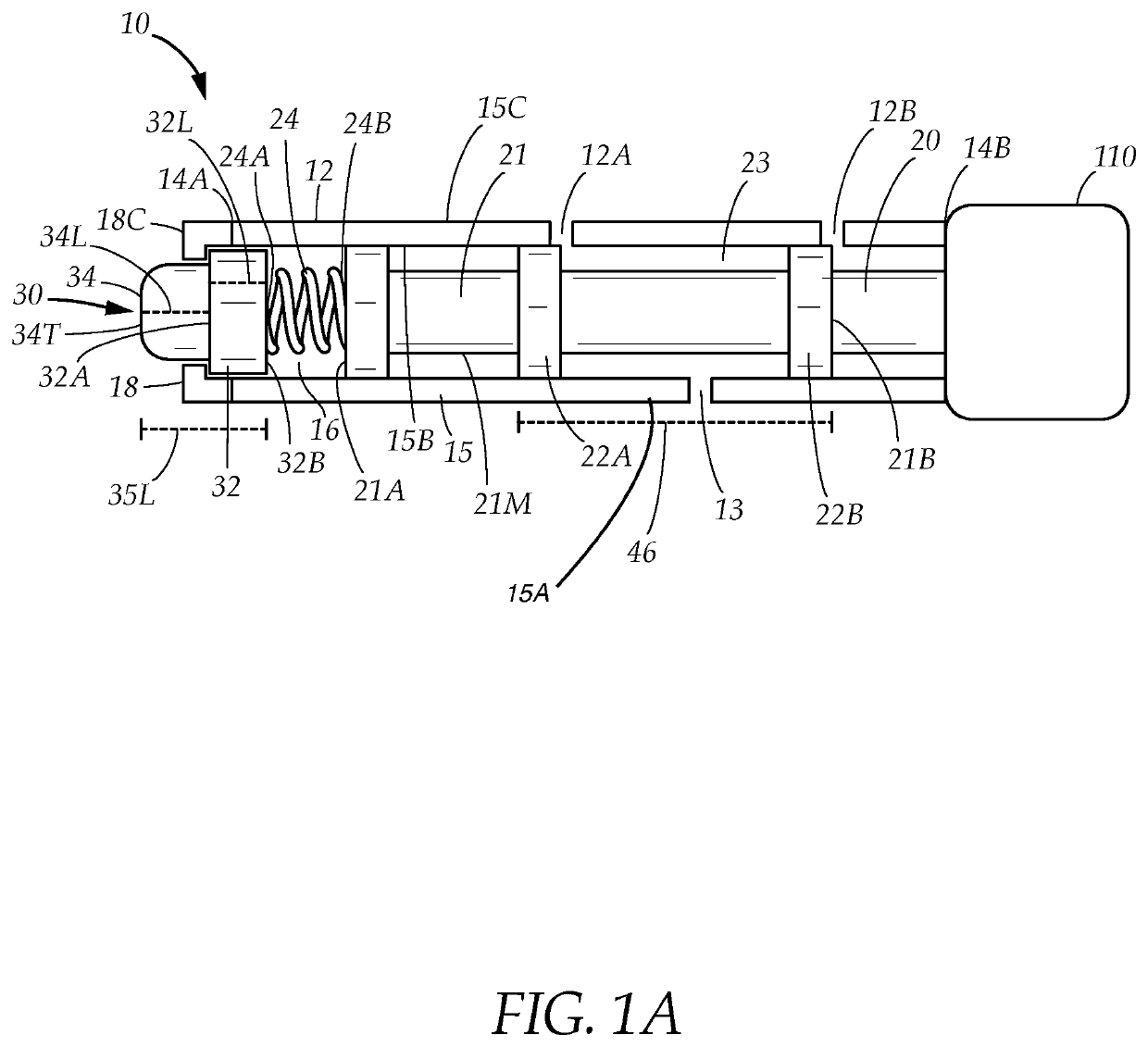
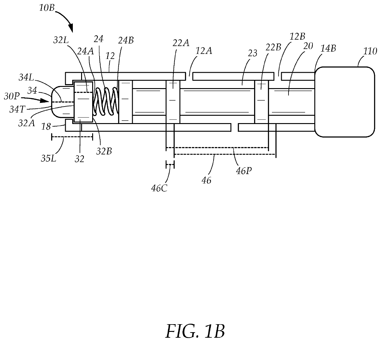
[0025]FIG. 1A illustrates a turbocharger control valve 10 for controlling a variable geometry turbocharger 50 as shown in FIGS. 2A-B. The turbocharger 50 is adapted for use with an internal combustion engine for powering vehicles such as cars or trucks, and increases the performance of the engine by harnessing exhaust gas to increase the engine's power output.

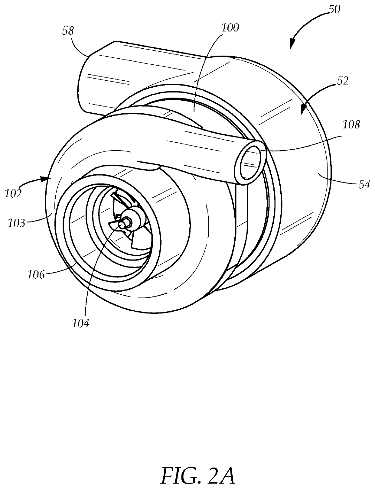
[0026]Referring to FIGS. 2A-B, the exemplary variable geometry turbocharger 50 depicted is known in the art and comprises a turbine assembly 52, a compressor assembly 102, and a central housing 100 which joins the compressor and turbine assemblies 102, 52. The turbocharger 50 is adapted to improve the efficiency and power of an internal combustion engine having one or more combustion chambers, an air intake to draw air into the combustion chambers, and an exhaust port to allow exhaust gas to exit, by harnessing the exhaust gas using the turbine assembly 52, which in turn drives the compressor assembly 102, causing the compresso...


PUM


Abstract

A turbocharger control valve having an extended feedback cap for altering the performance of a variable geometry turbocharger delivering boost pressure to an engine, the extended feedback cap has an increased cap length which displaces a spool within the turbocharger control valve to alter hydraulic fluid flow through the turbocharger control valve, causing the turbocharger to delay opening a variable inlet to release exhaust pressure, also causing the turbocharger to preemptively close the variable inlet to mitigate loss of exhaust back pressure and boost pressure without a command from a turbocharger control module.

Description

TECHNICAL FIELD[0001]The present disclosure relates generally to a turbocharger control valve. More particularly, the present disclosure relates to an improved control valve which improves turbocharger performance with minimal modification.BACKGROUND[0002]A turbocharger improves the efficiency of an internal combustion engine by harnessing the exhaust gas produced by the engine to power a turbine, which in turn rotates a compressor to deliver compressed air to the engine to increase the power and efficiency of the engine. Conventional turbochargers have turbines with fixed sizes and their performance characteristics are limited as a result. Large turbines are capable of producing large amounts of boost pressure, but are subject to longer “spool up” times as the volume of exhaust gas produced by the engine at low engine speeds is initially insufficient to turn the turbine wheel, requiring a steady buildup of exhaust gas pressure until the turbocharger can generate boost pressure. Tur...

Claims


Application Information

Patent Timeline
IPC IPC(8): F02B37/24F02D41/00
CPCF02B37/24F02D41/0007F05D2220/40F05D2240/12F05D2270/304F05D2270/3013F05D2270/44Y02T10/12F02B39/00F02D2250/34
Inventor EZRA, EYAL
Owner EZRA EYAL
Why Eureka
Try Eureka