Filter structure improvement

a filter structure and filter technology, applied in the field of filters, can solve problems such as affecting the character of filters, and achieve the effects of improving the characteristics of filters, improving the coupling capacitance of filters, and low insertion loss

Active Publication Date: 2018-06-21
CIROCOMM TECH CORP
View PDF1 Cites 1 Cited by
  • Summary
  • Abstract
  • Description
  • Claims
  • Application Information

AI Technical Summary

Benefits of technology

[0005]Therefore, a main objective of the present invention is to improve the characteristics of the filter structure and thus the metal pattern layer is disposed on the open surface in the present invention to increase the whole coupling capacitance of the filter structure to obtain the desired operating frequency band. In addition, the present invention has the effects of low insertion loss and out-band rejection.

Problems solved by technology

If the pattern is not designed properly on the filter surface, the characteristics of the filter will be affected.

Method used


Image

  • Filter structure improvement
  • Filter structure improvement
  • Filter structure improvement

Examples


first embodiment

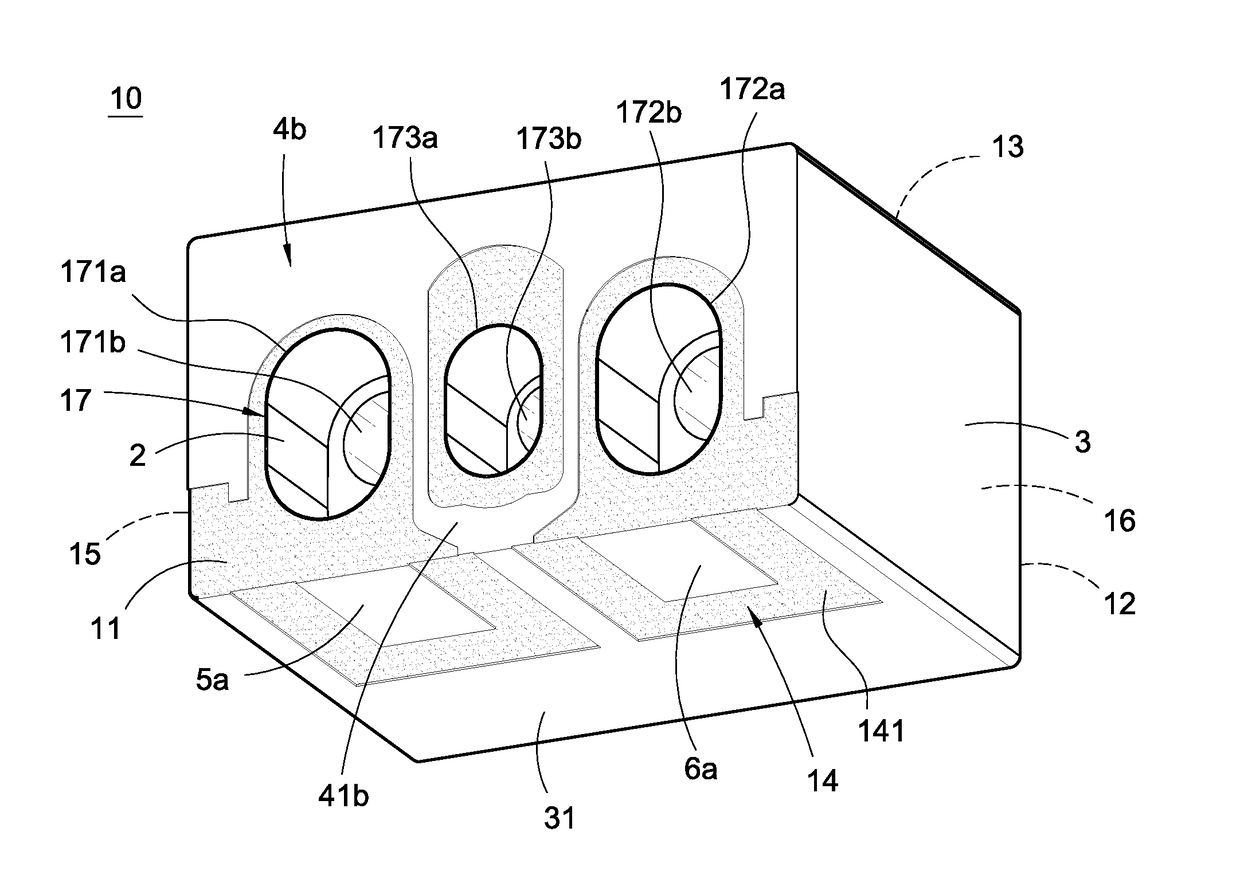
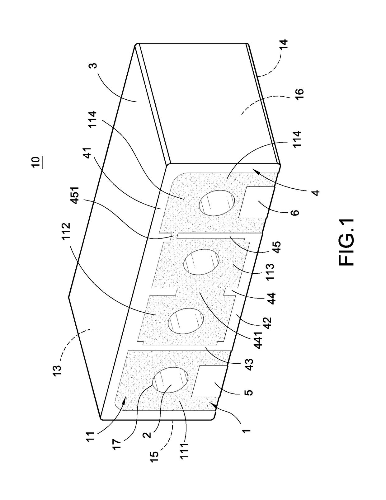
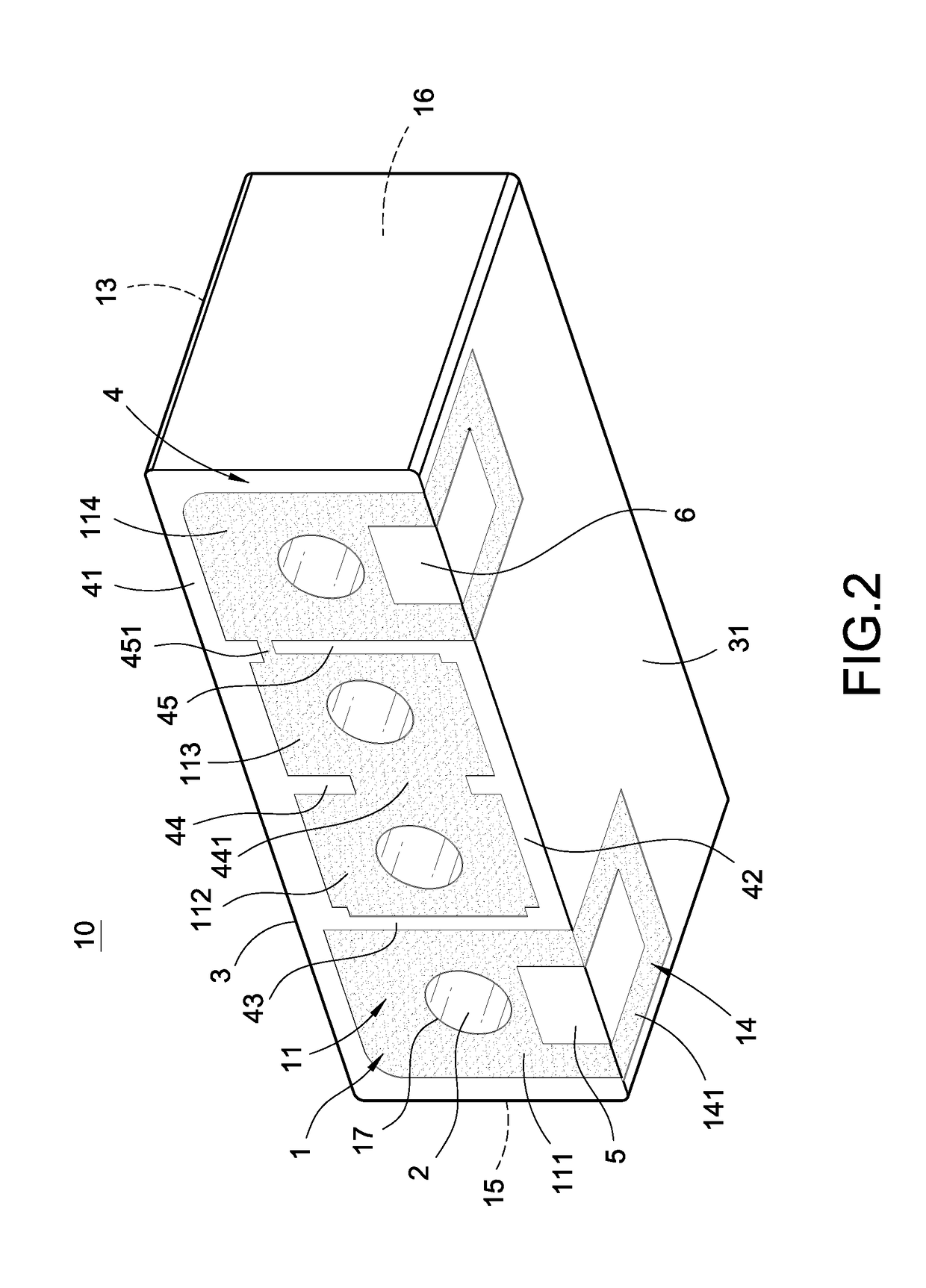
[0035]Please refer to FIGS. 1-3, which are the perspective schematic view, the bottom view, and the rear view of the filter structure improvement according to the present invention, respectively. As shown in the above figures, the filter structure 10 comprises a substrate 1, a plurality of resonance metal layers 2, a grounded metal layer 3, a metal pattern layer 4, an input electrode 5, and an output electrode 6. The internal metal layer 2, the grounded metal layer 3, the input electrode 5, and the output electrode 6 cover the substrate 1 to form a dielectric filter structure. The substrate 1 is a cuboid made of ceramic material with high dielectric coefficient and has an open surface 11, a short-circuit surface 12, a top surface 13, a bottom surface 14, and two side surfaces 15, 16 disposed thereon. The substrate 1 has a plurality of resonance holes 17 penetrating through the substrate 1. One end of each of the resonance holes 17 is disposed on the open surface 11 and the other end...

second embodiment

[0049]It is worth mentioning that the line section 45a of the metal pattern layer 4a in the second embodiment can be disposed on a common side of the resonance holes 17 such that the line section 45a and the resonance metal layers 2 in the resonance holes 17 can form coupling capacitance and inductance. As a result, the filter structure 10 can improve the reflection coefficient (S11) matching and the out-band rejection level to obtain the desired operating frequency band.

[0050]Please refer to FIG. 8, which is a perspective schematic view of the filter structure improvement according to the fourth embodiment of the present invention. As shown in FIG. 8, the current embodiment is roughly similar to the third embodiment. The difference is that the metal pattern layer 4b has an inversed E-like shape in the fourth embodiment. The grounded metal layer 3 of the inversed E-like shape is disposed on a common side of the resonance holes 17 and is electrically connected to the grounded metal l...


PUM


Abstract

A filter structure improvement includes a substrate, resonance layers, a grounded layer, a pattern layer, an input electrode, and an output electrode. The substrate has resonance holes in which the resonance layers are disposed. One end of the resonance hole is on the open surface and the other end of the resonance hole is on the short-circuit surface. The grounded layer is on the short-circuit surface, top surface, bottom surface, and side surfaces and is electrically connected to the resonance layers to form a short-circuit end. The input and output electrodes, electrically isolated from the grounded layer, are on the bottom or open surface of the substrate. The pattern layer, resonance layers, and grounded layer are arranged to have electrical properties of a filter structure of mutual coupling such that a desired frequency band is obtained by adjusting the pattern layer and the lengths of the resonance layers.

Description

BACKGROUND OF THE INVENTIONField of the Invention[0001]The present invention relates to a filter and in particular to a filter structure improvement of surface mount technology which can change the frequency response.Description of Prior Art[0002]It is well known that surface mount filters are widely used in LNB (Low Noise Block), GPS (Global Positioning System) and Wi-Fi systems. When these filters are applied to these communication systems, their functions are to filter out the noise accompanying the single received by the communications to ensure the qualities of transmission and receiving of the communication systems.[0003]The currently used filter comprises a substrate having plural resonance holes which penetrate through the substrate. One end of each of the resonance holes is disposed on an open surface; the other end of each of the resonance holes is disposed on a short-circuit surface. The short-circuit surface, the top surface, the bottom surface, and tow side surfaces of ...

Claims


Application Information

Patent Timeline
Patent Type & Authority Applications(United States)
IPC IPC(8): H01P1/205
CPCH01P7/065H01P1/2002H01P1/2056H01P1/205
Inventor CHOU, SHIN-HUICHEN, CHIN-HAOJHONG, YUE-CHENGLIN, YI-CHING
Owner CIROCOMM TECH CORP
Why Eureka
Try Eureka