
A belt conveyor idler roller replacement device

A belt conveyor and idler technology, applied in metal processing equipment, metal processing, manufacturing tools, etc., can solve the problems of long operation time, poor safety, and affecting the operation efficiency of the whole machine.

Active Publication Date: 2019-03-19
NORTHERN HEAVY IND GRP CO LTD
View PDF5 Cites 0 Cited by
  • Summary
  • Abstract
  • Description
  • Claims
  • Application Information

AI Technical Summary

Problems solved by technology

When the idler is damaged, the maintenance personnel need to loosen the tensioning device first, clean up the materials carried by the front and rear conveyor belts of the idler that needs to be maintained, and then find two lifting points or carry a shelf, and use the electric hoist to cooperate with the chain. The conveyor belt is hoisted and the damaged rollers are replaced manually, which is labor-intensive and low-efficiency for the maintenance personnel, and the complex environment on site will also pose hidden dangers to the safety of the maintenance personnel.
There are deficiencies in the existing idler replacement device: first, the labor intensity of manual handling and replacement is high and the operation time is long, which affects the operation efficiency of the whole machine; second, the site environment is harsh, which makes manual replacement difficult and poor in safety; Many, low work efficiency
In summary, the shortcomings of the traditional idler replacement device make the current manual replacement method seriously affect the operating efficiency of the whole machine

Method used


Image

  • A belt conveyor idler roller replacement device
  • A belt conveyor idler roller replacement device
  • A belt conveyor idler roller replacement device

Examples


Embodiment Construction

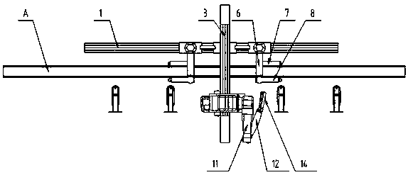
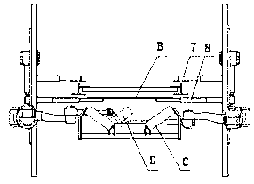
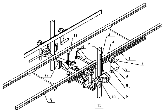
[0013] Referring to the accompanying drawings, a belt conveyor idler replacement device includes a first carriage 1, a first connecting plate 2, a second carriage 3, a second connecting plate 4, a supporting belt base 5, and a supporting belt base 6. The first telescopic arm 7, the second telescopic arm 8, the base 9, the base turntable 10, the big arm 11, the small arm 12, the gripper turntable 13, the gripper 14, the first carriage 1 is made of steel plate Composition, the slideway is arranged on the first carriage 1, and the first carriage 1 is fixed on the maintenance walking mechanism A that realizes the left and right movement of the idler roller replacement device of the belt conveyor. The first connecting plate 2 is composed of steel plates. It is fixed on the second connecting plate 4, and a slideway is set on the back of the second connecting plate 4. The second connecting plate 4 is connected with the first carriage 1, and the second carriage 3 is fixed on the first ...


PUM


Abstract

The invention discloses a carrier roller replacing device for a belt conveyor. The carrier roller replacing device comprises first sliding frames, first connecting plates, second sliding frames, second connecting plates, supporting belt bases, supporting belt base frames, first telescopic arms, second telescopic arms, bases, base rotating tables, large arms, small arms, gripper rotating tables andgrippers; slide ways are arranged on the first sliding frames, the first sliding frames are fixed on maintenance walking mechanisms A for realizing the left-and-right movement of the carrier roller replacing device of the belt conveyor; the first connecting plates are composed of steel plates, and are fixed on the second connecting plates; slide ways are arranged on the back surfaces of the second connecting plates, and the second connecting plates are connected with the first sliding frames; the second sliding frames are fixed on the first connecting plates for realizing the grabbing function and being moved up and down; and the supporting belt bases used for carrying the carrier roller replacing device of the belt conveyor are fixed on the second connecting plates. The carrier roller replacing device has the advantages of being safe and reliable, practicability is high, replacement automation of a carrier roller of the belt conveyor is realized, the maintenance process can be circularly carried out, and the carrier roller replacing device is applied to the technical field of bulk material conveying equipment.

Description

technical field [0001] The invention relates to a belt conveyor idler roller replacement device in the technical field of bulk material conveying equipment. Background technique [0002] At present, in the daily inspection and maintenance of belt conveyors, especially long-distance belt conveyors, the idler roller is the main part of its damage. It is distributed along the entire length of the conveyor, and its weight accounts for about 30% of the weight of the whole machine. The price accounts for about 20%-30% of the whole machine. When the idler is damaged, the maintenance personnel need to loosen the tensioning device first, clean up the materials carried by the front and rear conveyor belts of the idler that needs to be maintained, and then find two lifting points or carry a shelf, and use the electric hoist to cooperate with the chain. The conveyor belt is hoisted, and the replacement of the damaged idler roller is completed manually, which is labor-intensive and low-...

Claims


Application Information

Patent Timeline
Patent Type & Authority Patents(China)
IPC IPC(8): B23P19/04
Inventor 孟佳音高勇李宁杨帆魏雅丹孟浩董志宏吕斌宫良宵冯兴华孙新平
Owner NORTHERN HEAVY IND GRP CO LTD
Learn More