A resin-based wax pattern rapid prototyping mold

A molding mold and resin-based technology, applied in the field of resin-based wax mold rapid prototyping molds, can solve the problems of prone to errors, low molding rate of finished products, solidification of wax liquid, etc., so as to improve the yield of finished products and avoid premature cooling.

Active Publication Date: 2019-06-14
青岛海思威尔环保科技有限公司
View PDF12 Cites 0 Cited by
  • Summary
  • Abstract
  • Description
  • Claims
  • Application Information

AI Technical Summary

Problems solved by technology

[0003] In the process of making wax molds, it is necessary to pour melted wax liquid into the mold. For some simple parts, the yield of wax molds is still very high. However, for some thin-walled parts and parts with special-shaped holes, due to Difficult to remove the air, early cooling of the wax liquid and other reasons, so that the molding rate of the finished product is low, and when the mold is pouring, because the temperature of the mold is lower than the temperature of the wax liquid, the wax liquid will solidify in advance, resulting in insufficient pouring
[0004] Secondly, when the mold is cooling, since the molds are not poured at the same time, there is a time difference. Therefore, the cooling start time of each pouring mold needs to be recorded in order to determine the mold release time. However, this method is not only time-consuming and laborious, but also Mistakes are prone to occur. If the mould-making time is too early, it will easily cause damage to the wax model. If the mould-making time is too late, it will not be conducive to the rapid production of the enterprise.

Method used


Image

  • A resin-based wax pattern rapid prototyping mold
  • A resin-based wax pattern rapid prototyping mold
  • A resin-based wax pattern rapid prototyping mold

Examples


Embodiment Construction

[0027] The following will clearly and completely describe the technical solutions in the embodiments of the present invention with reference to the accompanying drawings in the embodiments of the present invention. Obviously, the described embodiments are only some, not all, embodiments of the present invention. Based on the embodiments of the present invention, all other embodiments obtained by persons of ordinary skill in the art without making creative efforts belong to the protection scope of the present invention.

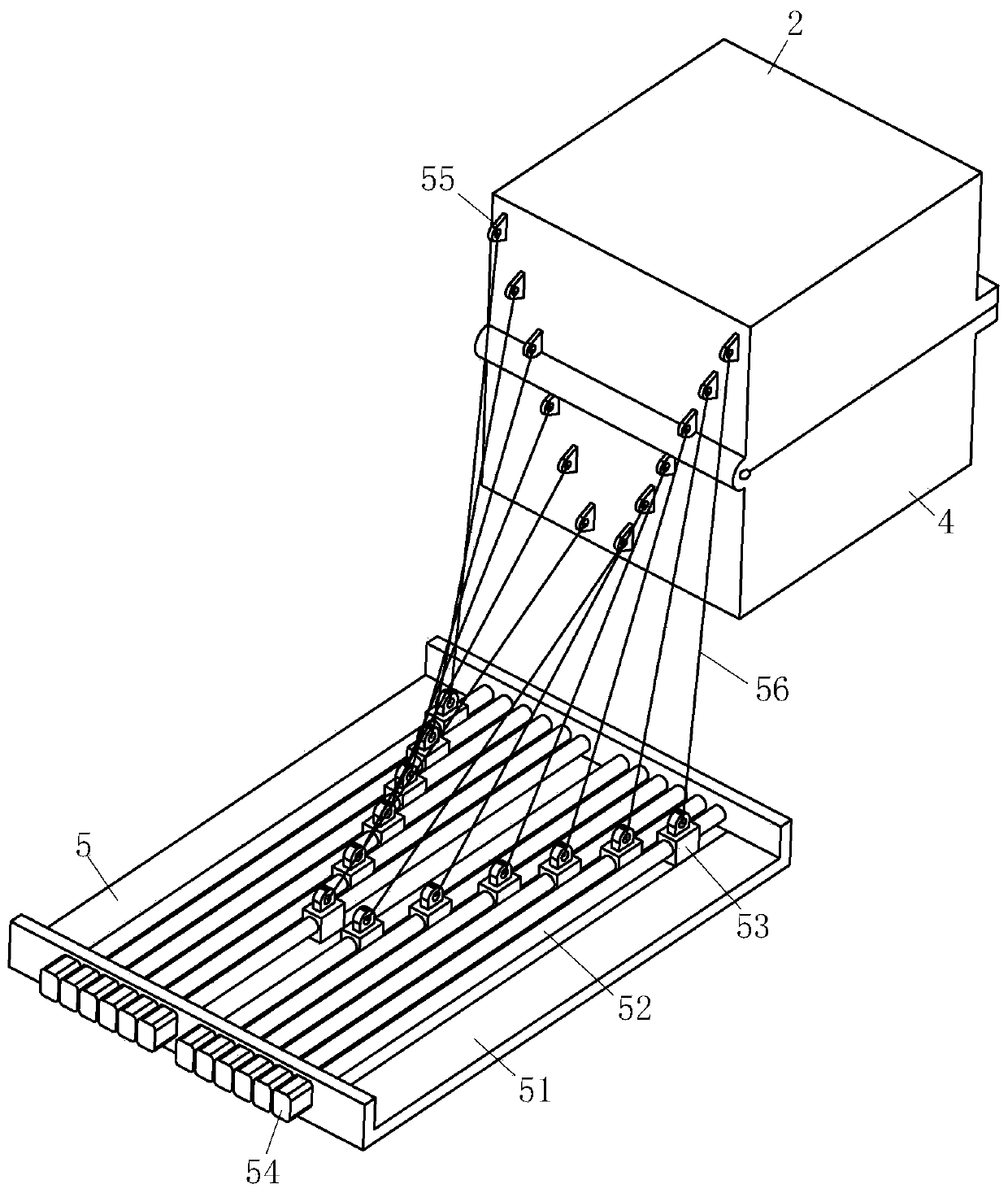
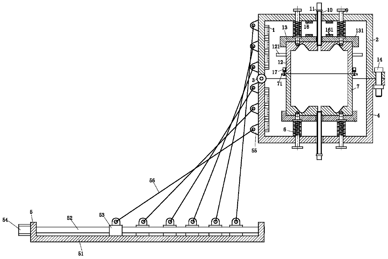
[0028] Such as Figure 1 to Figure 9 As shown, a resin-based wax pattern rapid prototyping mold according to the present invention includes an upper mold shell 2, a lower mold shell 4, an upper mold 12, a lower mold 7, a pouring tube 10, an oscillation module 13, a turning module 5, a heating The module 1 and the controller, the left ends of the upper mold shell 2 and the lower mold shell 4 are hinged together through the pin shaft 3, and the right ends of the...


PUM


Abstract

The invention relates to the field of lost wax casting, in particular to a rapid forming mold for a resin-based wax pattern. The rapid forming mold comprises an upper mold shell, a lower mold shell, an upper mold body, a lower mold body, casting tubes, vibration modules, a turnover module, heating modules and a controller; the left end of the upper mold shell and the left end of the lower mold shell are hinged together through a hinge pin; the upper mold body and the lower mold body are located inside the upper mold shell and the lower mold shell correspondingly and are elastically connected to the upper mold shell and the lower mold shell correspondingly through the vibration modules; the upper mold body and the lower mold body are connected through connecting pieces in a sealed mode; thevibration modules can vibrate the upper mold body and the lower mold body under the action of the turnover module; the turnover module can shake the upper mold body and the lower mold body; the two casting pipes are arranged, are connected to the upper mold body and the lower mold body separately in a threaded mold and penetrates upwards or downwards out of the upper mould shell or the lower mould shell; and the heating modules are arranged on the inner wall of the upper mold shell and the inner wall of the lower mold shell. The rapid forming mold has the advantages that air in the complex mold can be discharged, and the pattern forming rate can be effectively increased.

Description

technical field [0001] The invention relates to the field of wax pattern casting, in particular to a resin-based wax pattern rapid prototyping mold. Background technique [0002] Wax mold is a common casting method. First, the mold of the workpiece is made of aluminum, and then the step of injecting wax into the mold is called "waxing". At this time, the wax model is the same size as the real thing (the actual size is enlarged according to the casting shrinkage ratio), and then the surface of the wax model is covered with sand to a certain thickness. This step is called "staining sand". After the foundry sand is bonded, the sand-covered wax mold is put into water to boil, and the wax is boiled to leave a sand shell. This step is called "boiling wax". Finally, the sand shell is buried in the casting sand pit and the molten iron is extended to the sand shell. Pour in, and the molten iron left in the sand mold cools down and becomes a casting. [0003] In the process of makin...

Claims


Application Information

Patent Timeline
Patent Type & Authority Patents(China)
IPC IPC(8): B29C39/26B29C39/38B29C39/22B22C7/02
Inventor 陈壮壮李世群张伟
Owner 青岛海思威尔环保科技有限公司
Why Eureka
Try Eureka