Seismometer

A seismograph and contact switch technology, applied in the field of seismographs, can solve the problems of unsuitable seismographs and large volumes of earthquake early warning devices, and achieve the effect of small volume

Inactive Publication Date: 2018-01-05
杨泉
View PDF0 Cites 1 Cited by
  • Summary
  • Abstract
  • Description
  • Claims
  • Application Information

AI Technical Summary

Problems solved by technology

[0002] Existing earthquake early warning devices are large in size, and there is no seismic instrument suitable for ordinary households

Method used


Image

  • Seismometer

Examples


Embodiment Construction

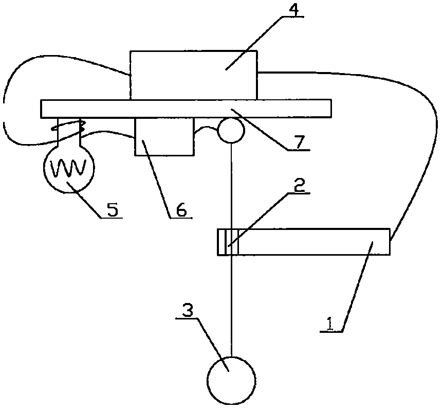
[0010] As shown in the figure, a seismograph includes a contact switch 1, a counterweight ball 3, a power supply 4, a light bulb 5 and an alarm 6. The contact switch 1 is provided with a through hole 2, and the plumb line of the counterweight ball 3 passes through the channel. Hole 2, contact switch 1 is connected in series with power supply 4, bulb 5 and alarm 6 by wire, and power supply 4, bulb 5 and alarm 6 are all fixedly arranged on the fixed plate 7.

[0011] In a preferred solution, the plumb line of the weight ball 3 is a metal wire, which forms a loop with the wire.

[0012] By adopting the above-mentioned structure, its volume is small, and it can efficiently and accurately predict earthquakes, which is more suitable for ordinary households.


PUM


Abstract

A seismograph, including a contact switch, a weighted ball, a power supply, a light bulb and an alarm, the contact switch is provided with a through hole, the plumb line of the weighted ball passes through the through hole, the contact switch is connected with the power supply, the light bulb and the alarm through a wire The devices are connected in series, and the power supply, light bulb and alarm are all fixedly arranged on the fixed plate. The plumb line of the counterweight ball adopts a metal wire to form a loop with the wire. By adopting the above structure, under the condition of vibration, the small ball swings with the vibration, so that the plumb line is in contact with the contact switch, thereby forming a loop, making the bulb light up, and the alarm alarm, so as to realize the early warning work of the earthquake, with volume Small, able to accurately predict the characteristics of earthquakes.

Description

technical field [0001] The invention relates to a seismograph, in particular to a seismograph. Background technique [0002] Existing earthquake early warning devices are all relatively large in size, and are not applicable to earthquake instruments in general households. Contents of the invention [0003] The technical problem to be solved by the present invention is to provide a seismograph, which has a small volume and can efficiently and accurately predict earthquakes, and is more suitable for ordinary households. [0004] In order to solve the above technical problems, the technical solution adopted in the present invention is: a seismograph comprising a contact switch, a weighted ball, a power supply, a light bulb and an alarm, the contact switch is provided with a through hole, and the vertical line of the weighted ball Through the through hole, the contact switch is connected in series with the power supply, light bulb and alarm through wires, and the power supply...

Claims


Application Information

Patent Timeline
IPC IPC(8): G01V1/18
Inventor 杨泉
Owner 杨泉
Why Eureka
Try Eureka