A lens drive device

A lens driving device and lens body technology, applied in installation, optics, instruments, etc., can solve problems such as fracture, deformation of the arm 905c, and falling off of the buffer 917

Active Publication Date: 2018-01-05
ALPS ALPINE CO LTD
View PDF5 Cites 5 Cited by
  • Summary
  • Abstract
  • Description
  • Claims
  • Application Information

AI Technical Summary

Problems solved by technology

[0008] However, since the buffer member 917 is provided as the elastically deformable arm portion 905c spanned between the movable side fixing portion 905a and the fixed side fixing portion 905b of the spring member, there is a problem in

Method used


Image

  • A lens drive device
  • A lens drive device
  • A lens drive device

Examples


no. 1 Embodiment approach

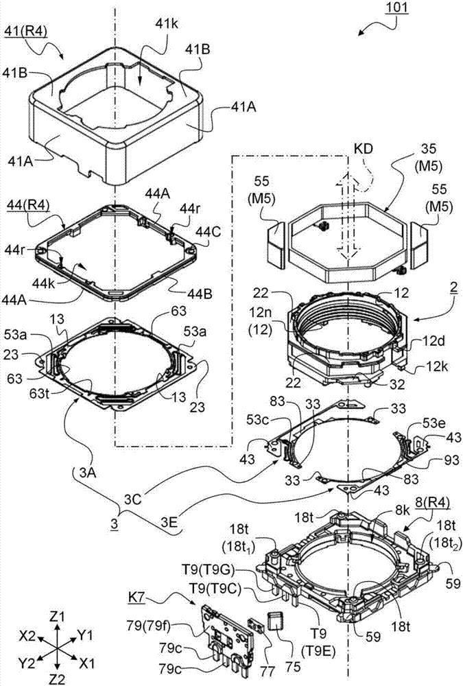
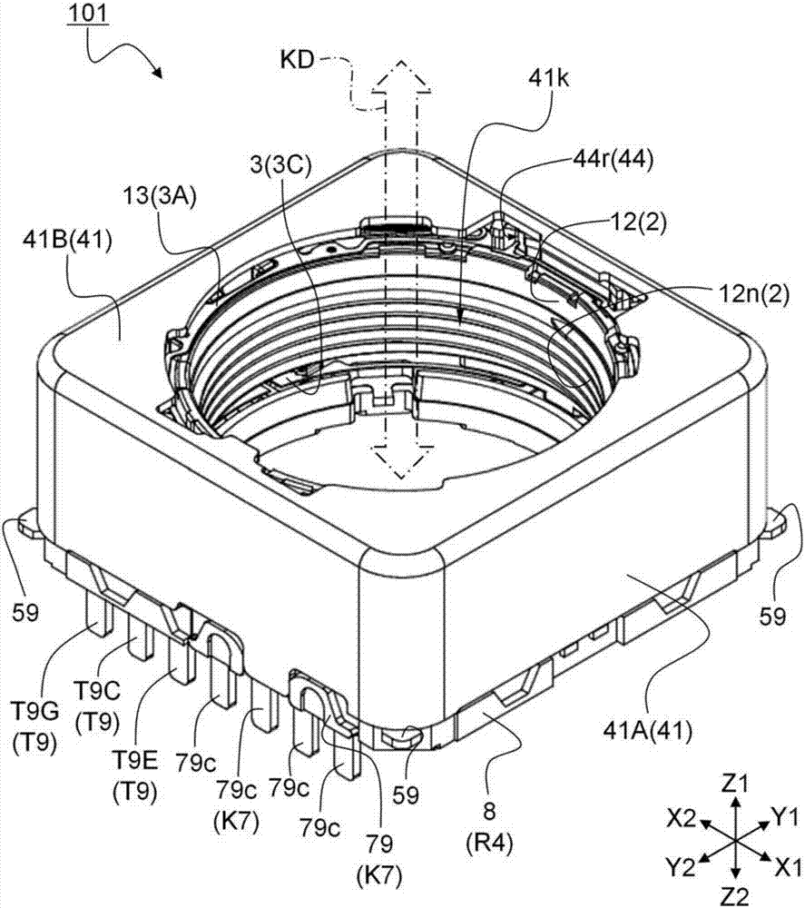
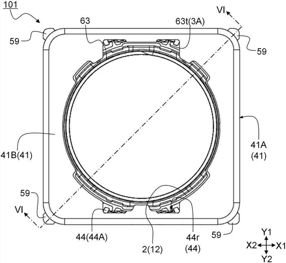
[0060] figure 1 It is an exploded perspective view illustrating the lens driving device 101 according to the first embodiment of the present invention. figure 2 It is a perspective view illustrating the lens driving device 101 according to the first embodiment of the present invention. Figure 3A Viewed from Z1 side figure 2 A top view of the lens driving device 101, Figure 3B Viewed from Y2 side figure 2 The front view of the lens driving device 101. Figure 4A will be figure 2 A perspective view in which the case 41 serving as the fixed-side member R4 of the shown lens driving device 101 is omitted, Figure 4B will be Figure 4A The illustrated perspective view of the frame-shaped member 44 and the position detection unit K7 is further omitted. Figure 5A Viewed from Z2 side figure 2 The bottom view of the lens driving device 101, Figure 5B will be Figure 5A The bottom view of the base part 8 is shown with omission. Figure 6 yes Figure 3A The shown cro...

Deformed example 1

[0133] In the above-mentioned first embodiment, it is preferable that the extended portions 63 extended from the opposing and adjacent first portions 13 are connected to form one connecting portion, but the present invention is not limited thereto. For example, It is a structure in which the part facing and adjacent to the horizontal bar part 73 is notched.

Deformed example 2

[0135] In the above-described first embodiment, a set of sides of the frame-shaped member 44 facing each other is the first extending portion 44A, and the other set of sides intersecting the first extending portion 44A is configured as the second extending portion 44B. , but not limited to this. For example, as long as the first extensions are respectively extended from a set of opposite sides and arranged along the set of sides respectively, and the second extensions 44B are respectively extended from the other set of sides and arranged along the set (another set of sides). One group) side can be set separately. That is, for example, the first extending portion may be separately provided along one set of sides, or the second extending portion may be separately provided along another set of sides.


PUM


Abstract

A lens drive device (101) capable of ensuring that the vibration in the optical axis direction converges in a short period of time even when a strong impact is applied due to, for example, a drop is provided with a cylindrical lens holding member (2) that can hold a lens body; a force applying member (3) that supports the lens holding member so as to be movable in the optical axis direction; a fixing side member (R4) that fixes a part of the force applying member; a drive mechanism (M5) that moves the lens holding member in the optical axis direction. The force applying member has an upper leaf spring (3A) fixed to an upper portion of the lens holding member; the upper leaf spring having a first portion (13) fixed to the lens holding member, a second portion (23) fixed to the fixing side member, an elastic arm portion (53a) provided between the first portion and the second portion, and an extending portion (63) extending from the first portion; a damping port (GE) is arranged to striding over the extending portion and the fixing side member.

Description

technical field [0001] The present invention relates to a lens driving device mounted in, for example, a portable device with a camera. Background technique [0002] In recent years, it has become common to mount camera mechanisms in portable devices represented by mobile phones. In addition to the demand for miniaturization, the demand for driving the lens body (the lens barrel on which the lens is mounted) with high precision has also increased regarding the lens driving device, which is the main part of the camera mechanism mounted on this small portable device. . As a lens driving device satisfying these two requirements, a technique in which a magnetic circuit for driving a lens holder (lens holding member) holding a lens body is provided around the lens holder is known. [0003] As such a lens driving device, Patent Document 1 (conventional example) proposes a lens driving device 901 as shown in FIG. 13 . Figure 13A and Figure 13B It is a figure explaining the len...

Claims


Application Information

Patent Timeline
IPC IPC(8): G02B7/02G02B7/04
Inventor 深井泰州加藤拓也矢岛英治郎
Owner ALPS ALPINE CO LTD
Why Eureka
Try Eureka