Rotating lifting device
A technology of lifting device and rotating block, applied in the direction of spray device, spray device with movable outlet, etc., can solve the problems of inability to control the speed, affect the processing effect, operator fatigue, etc., and achieve the effect of accurate swing angle and speed
- Summary
- Abstract
- Description
- Claims
- Application Information
AI Technical Summary
Problems solved by technology
Method used
Image
Examples
Embodiment 1
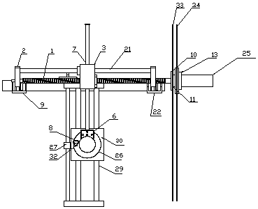
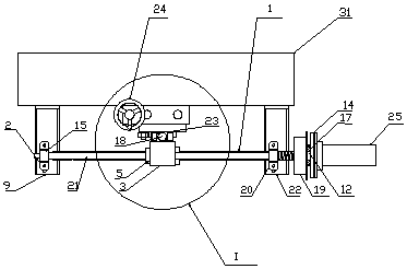
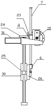
[0023] The rotary lifting device includes a fixed bracket (I), a servo motor (25), a hand wheel (24), a moving mechanism (II), a lifting mechanism (III) and a working plate (26) for installing tools, It is characterized in that: the servo motor (25), the hand wheel (24), the moving mechanism (II) and the lifting mechanism (III) are installed on a fixed bracket (I); the servo motor (25) is connected to the moving mechanism (II) ) And drive a moving block (3) on the mechanism to move left and right. The moving block (3) is connected to a lifting moving block (6) on the lifting mechanism through a swing rod (7) and driving it to rotate; the hand wheel (24) is connected to the lifting mechanism and drives one of the lifting blocks (30) ) For lifting movement; the working turntable (26) is fixedly connected with the lifting and rotating block (6), and the working turntable (26) and the lifting block (30) are coaxially and rotationally connected. Operating the servo motor (25) and / o...
Embodiment 2
[0025] The fixed bracket (I) includes square steel (31), L-shaped plate armour (21) and L-shaped plate B (22). The square steel plate (31) is welded to the original work equipment, and the L-shaped plate armour (9) ) And L-shaped plate B (22) are fixed on the square steel (31).
[0026] The moving mechanism (II) includes a ball screw (1), a screw mounting seat (2), a moving block (3), a rotating block (4), a linear bearing (5), an adapter block (6), a pendulum Rod (7), flange (10), waterproof gasket (11), adapter sleeve (12), motor seat (13), clamping plate (14), bearing (15, 16, 17), mold guide Cover (18), bending piece (19), screw mounting seat B (20), guide rod A (21), cover (23), inner plate (33) and outer plate (34), the screw is installed The seat A (2) and the screw mounting seat B (20) are respectively fixed on the L-shaped plate A (9) and the L-shaped plate B (22) to support the guide rod A (21) and the ball screw
[0027] (1) The ball screw (1) is matched with the screw...
Embodiment 3
[0029] The lifting mechanism (Ⅲ) includes a U piece (8), a hand wheel (24), a screw nut (27), a common screw (28), a guide rod B (29) and a lifting block (30). The block (30) is connected with the working turntable (26). After inserting the U (8) piece to push up the spring pin (32), the working turntable (26) can rotate around the axis relative to the lifting block (30). When the swing lever ( 7) When swinging, the working plate (26) rotates with the swing lever (7) in the moving mechanism (II) to complete the rotation. The lifting block (30) is slidingly sleeved on the guide rod B (29) and can move up and down along the guide rod B (29). After the bolts on the back of the lifting block (30) are locked, its position is fixed; the screw nut (27) ) Cooperate with the ordinary screw (28) and fix it on the side of the lifting block (30). The top of the ordinary screw (28) is equipped with a hand wheel (24) to cooperate. Turn the hand wheel to drive the screw nut (27) and the lifti...
PUM
 Abstract
Description
Claims
Application Information
 - R&D
- Intellectual Property
- Life Sciences
- Materials
- Tech Scout
- Unparalleled Data Quality
- Higher Quality Content
- 60% Fewer Hallucinations
Browse by: Latest US Patents, China's latest patents, Technical Efficacy Thesaurus, Application Domain, Technology Topic, Popular Technical Reports.
© 2025 PatSnap. All rights reserved.Legal|Privacy policy|Modern Slavery Act Transparency Statement|Sitemap|About US| Contact US: help@patsnap.com


