
Side formwork placement method for PC (Personal Computer) numerical control production line

A production line and side mold technology, applied in the field of side mold placement of PC numerical control production line, can solve the problems of inability to adjust, easy leakage of concrete liquid, poor sealing of ends and bottoms, etc., so as to reduce waste of resources and reduce investment costs. , to achieve the effect of generality

Active Publication Date: 2018-01-09
南阳精工匠人装配建筑科技有限公司
View PDF3 Cites 3 Cited by
  • Summary
  • Abstract
  • Description
  • Claims
  • Application Information

AI Technical Summary

Problems solved by technology

In the pouring of PC components, the size of the side formwork is often fixed and cannot be adjusted. At present, there are retractable side formwork structures on the market, but after the side formwork is used, the sealing performance of the end and the bottom is not good, and the concrete liquid is easy to leakage

Method used


Image

  • Side formwork placement method for PC (Personal Computer) numerical control production line
  • Side formwork placement method for PC (Personal Computer) numerical control production line

Examples


Embodiment Construction

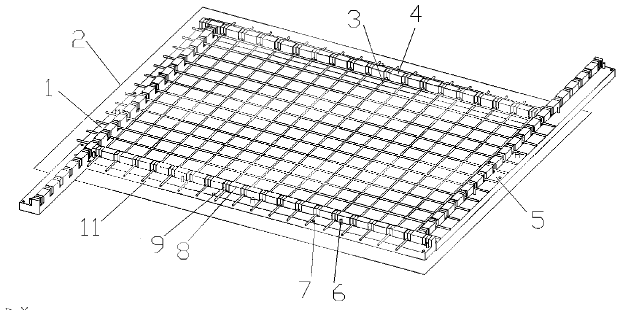
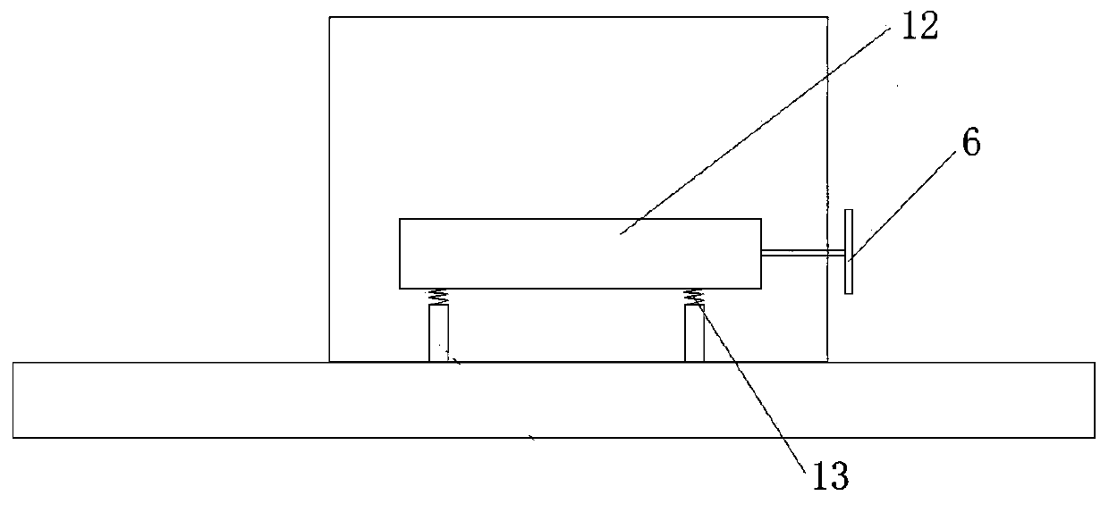
[0017] See attached figure 1 and figure 2 It is an embodiment of the present invention.

[0018] A method for placing side molds for a PC numerical control production line, which is realized through the following steps: 1) Making side molds: respectively making a first side mold 11, a second side mold 5, a third side mold 4, and a fourth side mold 1 , each side mold includes a base body and a plurality of fixed blocks 8 located on the surface of the base body, each fixed block 8 is provided with an inflatable bag 9 at both ends, the inside of the base body is provided with an inflation pipe, and the surface is provided with the Inflatable joints 7 connected by inflatable pipelines, the inflatable pipelines are also connected to each inflatable bag 9 respectively; a plurality of powerful magnet devices are also provided inside the base body, and the powerful magnet devices include powerful magnets 12 and are connected with the powerful magnets. 12 connected magnetic switches...


PUM


Abstract

The invention discloses a side formwork placement method for a PC (Personal Computer) numerical control production line. The method comprises the following steps of manufacturing a first side formwork, a second side formwork, a third side formwork and a fourth side formwork, wherein each side formwork comprises a base and a plurality of fixing blocks arranged at the surface of the base; accordingthe size of a PC component needing to be built, placing the first side formwork, the second side formwork, the third side formwork and the fourth side formwork on a working table, and moving accordingto the component size until the size requirement of the component is met; and switching on a magnetic switch, and tightly adsorbing the first side formwork, the second side formwork, the third side formwork and the fourth side formwork onto the working table. Compared with the prior art, according to the side formwork placement method for the PC numerical control production line provided by the invention, not only can the placement positions of the side formworks be freely changed according to the size of the PC component, but also a sealing performance of each side framework after being placed is favorable, leakage cannot be caused easily, convenience and efficiency in use are realized, and the effect is good.

Description

technical field [0001] The invention relates to the technical field of assembly building, in particular to a method for placing side forms for a PC numerical control production line. Background technique [0002] At present, the central government and local governments at all levels have introduced many support and encouragement measures for prefabricated buildings, rapidly promoting the development of the "prefabricated construction" industry. Construction companies are very sensitive to industry policies. In order to seize the opportunity, some companies began to quickly enter this industry. There is no doubt that it has become a hot word in the construction industry in recent years. Prefabricated buildings are the result of technological upgrading. In fact, the core of technology is the means to realize prefabricated buildings, that is, the industrialization and informatization of design, production, and construction processes. Only when all the means of realization are...

Claims


Application Information

Patent Timeline
Patent Type & Authority Applications(China)
IPC IPC(8): B28B7/00
Inventor 刘品潇蔡广宇马金发宗荣珍郑雄文张林海马海鑫
Owner 南阳精工匠人装配建筑科技有限公司
Learn More