Energy-saving ink-jet device

An inkjet device and energy-saving technology, applied in printing devices, printing, etc., can solve problems such as low intelligence, poor environmental protection, and low work efficiency, and achieve improved cleanliness, improved safety, and improved safety Effect

Inactive Publication Date: 2018-01-12
天津圣文纸制品股份有限公司
View PDF1 Cites 2 Cited by
  • Summary
  • Abstract
  • Description
  • Claims
  • Application Information

AI Technical Summary

Problems solved by technology

[0005] The technical scheme adopted by the present invention to solve the problems of not saving resources, poor environmental protection effect, low work efficiency, low degree of intelligence and high cost in the known technology is: an energy-saving inkjet device includes a workbench, a lifting rod , a slider, a connecting column, a sliding shaft, a drying device, a cooling device, a remote control structure, an inkjet device, an isolation door, a conveyor belt, a transmission shaft, a motor, a printing device, a sterilizing device, and the lifting rod is set on the isolation door The upper part; the slider is arranged on the upper part of the inkjet device; the sliding shaft is arranged on the lower part of the connecting column; the drying device is arranged on the left side of the cooling device; the remote control structure is arranged on The upper right part of the workbench; the inkjet device is arranged on the left side of the printing equipment; the conveyor belt is arranged on the upper part of the transmission shaft; the sterilization device is arranged on the left side of the lifting rod; the remote control structure Including a display screen, a button console, a base, and an alarm lamp, the display screen is set on the upper part of the button console; the alarm light is set on the right side of the button console

Method used


Image

  • Energy-saving ink-jet device
  • Energy-saving ink-jet device

Examples


Embodiment Construction

[0018] In order to further understand the invention content, characteristics and effects of the present invention, the following examples are given, and detailed descriptions are as follows in conjunction with the accompanying drawings:

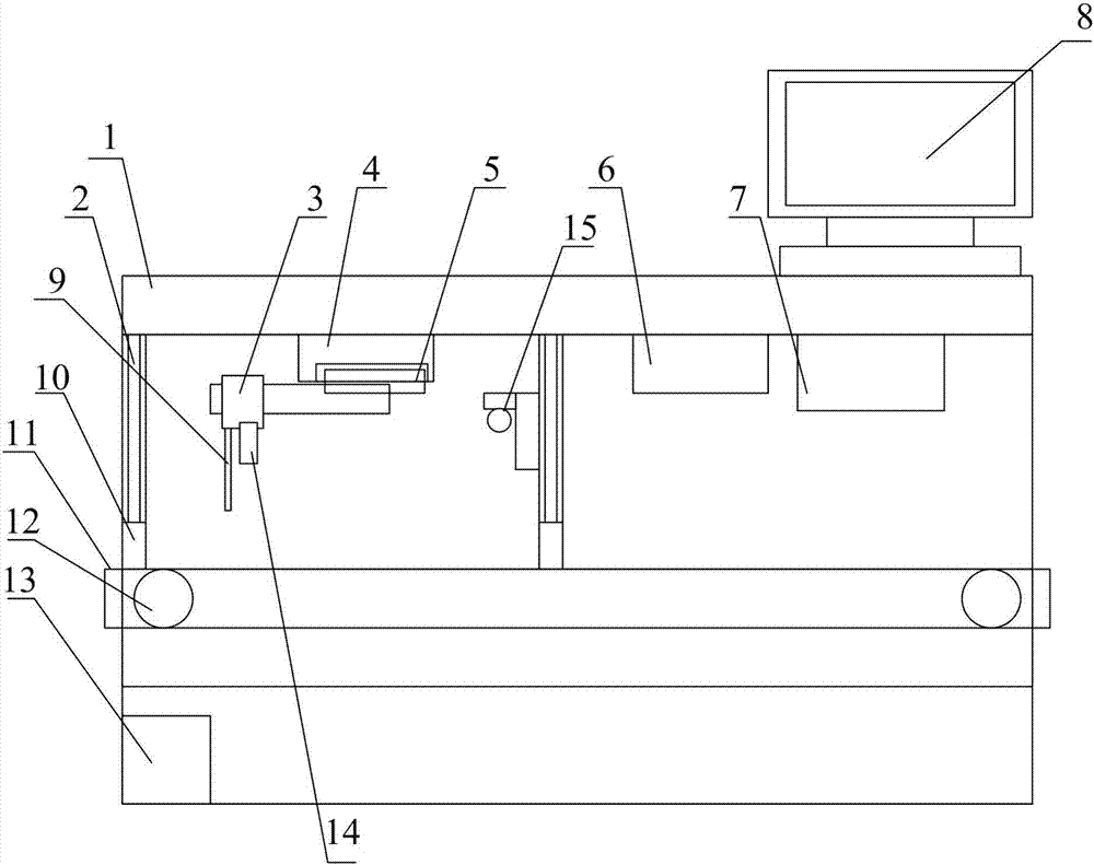
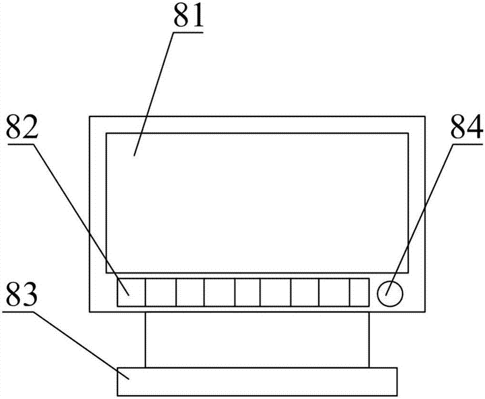
[0019] see figure 1 and figure 2 :

[0020] This specific embodiment adopts the following technical solutions: an energy-saving inkjet device includes a workbench 1, a lifting rod 2, a slider 3, a connecting column 4, a sliding shaft 5, a drying device 6, a cooling device 7, and a remote control structure 8 , inkjet device 9, isolation door 10, conveyer belt 11, transmission shaft 12, motor 13, printing equipment 14, sterilizing device 15, described elevating rod 2 is arranged on the top of isolation door 10; Described slider 3 is arranged on The upper part of the inkjet device 9; the sliding shaft 5 is arranged on the lower part of the connecting column 4; the drying device 6 is arranged on the left side of the cooling device 7; the remot...


PUM


Abstract

The invention provides an energy-saving ink-jet device which comprises a workbench, a lifting rod, a slider, a connecting column, a sliding shaft, a drying device, a cooling device, a remote control structure, an ink-jet device, isolation doors, a conveying belt, a conveying shaft, a motor, a printing device and a sterilization device, wherein the lifting rod is arranged at the upper part of the isolation door, the sliding device is arranged on the upper portion of the ink-jet device, the remote control structure comprises a display screen, a button control bench, a base and an alarm lamp, thedisplay screen is arranged on the upper portion of the button control bench, and the alarm lamp is arranged on the right side of the button control table. According to the invention, the remote control structure and the isolation doors are arranged, and the alarm lamp specifically adopts an acousto-optic alarm lamp, so that a user is reminded of the current working state and an alarm can be givenout in time when accidents happen. The safety is improved, and the two isolation doors are arranged, so that the cleanness degree can be improved, the safety degree can be improved, and the usage canbe guaranteed.

Description

technical field [0001] The invention belongs to the technical field of printing, and in particular relates to an energy-saving inkjet device. Background technique [0002] At present, the domestic table screen printing industry is relatively backward, and most of them are still manually operated. The screen frame is placed manually and the color is printed. The Chinese patent number is CN201010533533.8. The machine includes a frame, a treadmill printing mechanism, a transmission device and an electrical controller. The treadmill printing mechanism moves on the frame through the transmission device, and it is characterized in that the frame is provided with an air supply pipe, and the supply The air pipe is provided with several air source interfaces, and the treadmill printing mechanism is provided with an air storage cylinder for its printing. The air storage cylinder is provided with an air source connector, and the air source connector is connected to the air source The ...

Claims


Application Information

Patent Timeline
Patent Type & Authority Applications(China)
IPC IPC(8): B41J2/435B41J11/00B41J29/17B41J29/393B41J29/46
Inventor 李庭庄
Owner 天津圣文纸制品股份有限公司
Why Eureka
Try Eureka