Electrocoagulation cutter

An electric coagulation cutter and coagulation cutter technology, applied in the field of medical devices, can solve problems such as inability to drain, fix the space angle of the electric hook, and blockage of the front hole of the functional tube, so as to improve surgical safety, improve control performance, and avoid risks. Effect

Pending Publication Date: 2018-01-16
广东弘和医疗器械制造有限公司
View PDF6 Cites 6 Cited by
  • Summary
  • Abstract
  • Description
  • Claims
  • Application Information

AI Technical Summary

Problems solved by technology

[0004] The above-mentioned technical solution has the following defects: first, there are many large-angle bends in the negative pressure suction pipeline, which causes noise during the clinical operation and affects the doctor's operating mood; second, the space angle of the electric hook is fi

Method used


Image

  • Electrocoagulation cutter
  • Electrocoagulation cutter
  • Electrocoagulation cutter

Examples


Embodiment Construction

[0029] The technical solutions of the present invention will be clearly and completely described below in conjunction with the accompanying drawings. Apparently, the described embodiments are some of the embodiments of the present invention, but not all of them. Based on the embodiments of the present invention, all other embodiments obtained by persons of ordinary skill in the art without making creative efforts belong to the protection scope of the present invention.

[0030] In the description of the present invention, it should be noted that the terms "center", "upper", "lower", "left", "right", "vertical", "horizontal", "inner", "outer" etc. The indicated orientation or positional relationship is based on the orientation or positional relationship shown in the drawings, and is only for the convenience of describing the present invention and simplifying the description, rather than indicating or implying that the referred device or element must have a specific orientation, ...


PUM


Abstract

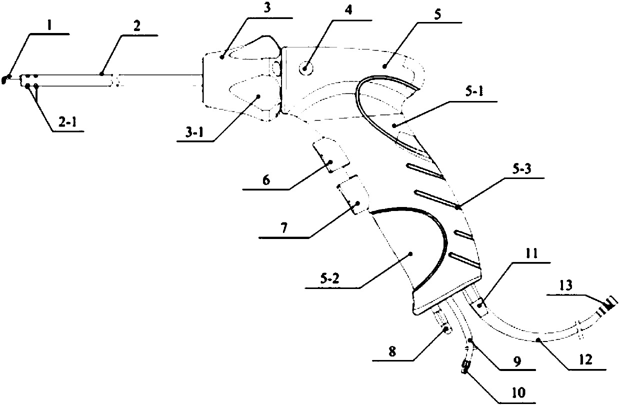
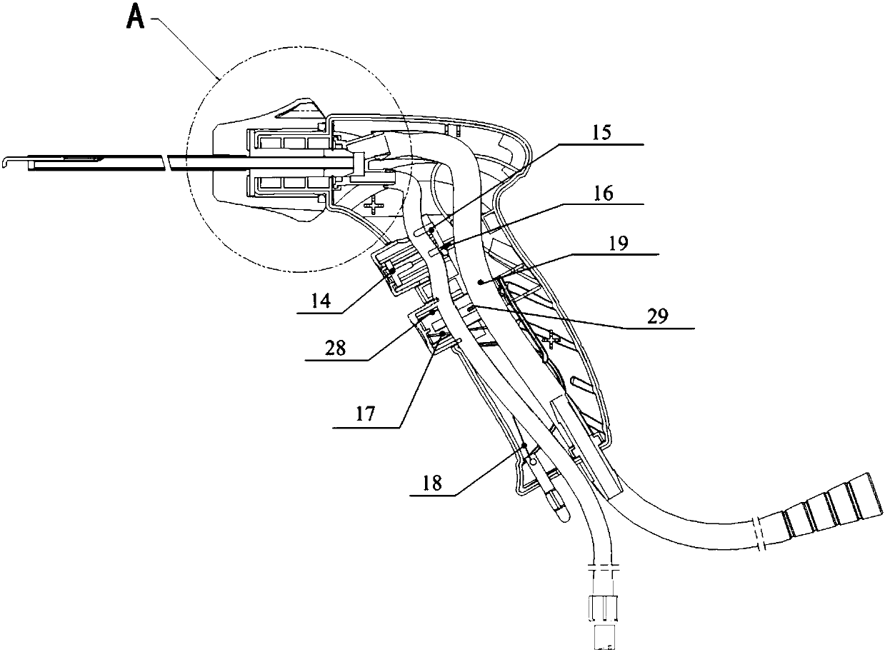
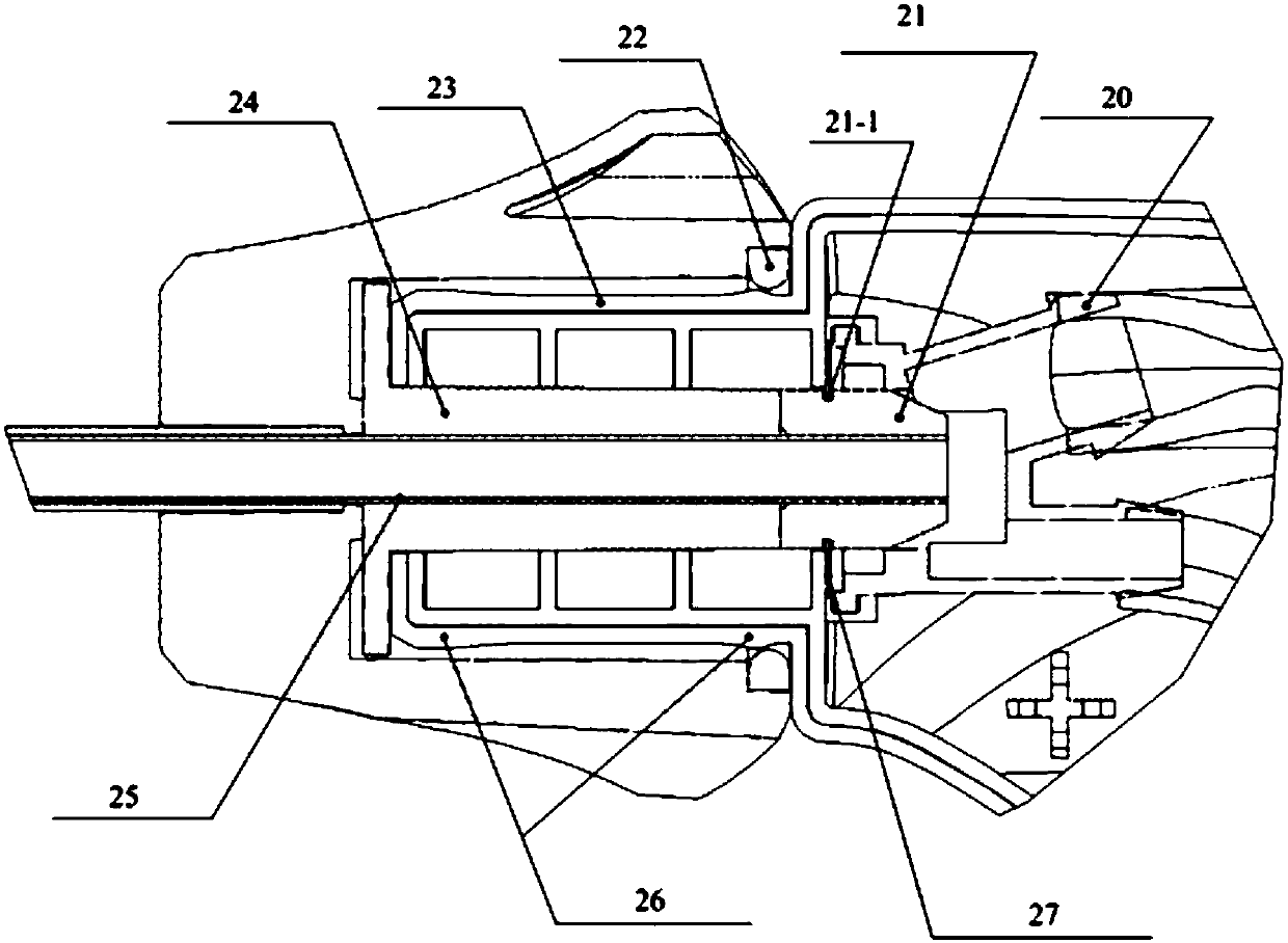
The invention discloses an electrocoagulation cutter. The electrocoagulation cutter comprises a handle, a metal pipe, a functional pipe, a washing pipe, a transition pipe, a power line and a pipe switch; a cavity is formed in the handle; the metal pipe is used for providing a channel for fluid; a cutter head mounting position is arranged at the front end of the metal pipe; the functional pipe covers the exterior of the metal pipe in a sleeving mode; the functional pipe can conduct reciprocating motion in the axial direction relative to the metal pipe, and when the functional pipe moves towardthe front end of the metal pipe, the cutter head mounting position can be covered; the washing pipe is communicated with the metal pipe; the transition pipe is communicated with the metal pipe; the power line is connected with the metal pipe and used for transmitting electric signals of electrocoagulation or cutting to a cutter head in the cutter head mounting position; the pipe switch is used forturning on or turning off the washing pipe or the channel between the transition pipe and the metal pipe. Electrocoagulation or cutting work and washing or absorbing work on a targeted area can be achieved through signal stimulation of the power line, and the operation performance of the electrocoagulation cutter is improved.

Description

technical field [0001] The invention relates to the technical field of medical instruments, in particular to an electrocoagulation cutter. Background technique [0002] With the development of science and technology, medical devices are developing along the mainstream direction of minimizing surgical trauma under the premise of ensuring safety and effectiveness, especially the popularization of laparoscopic surgery in urology, gynecology, abdominal surgery and other fields, which promotes Related medical devices continue to pursue more minimally invasive clinical effects. [0003] The Chinese patent with the application number 201510760113.6 discloses a medical device product with washing, suction, electrocoagulation, and cutting functions, which includes a housing, a control device, a tubular electrode and an electric hook connected to one end of the tubular electrode. There is a T-shaped pipe at the tail. The T-shaped pipe includes a horizontal pipe and a vertical pipe co...

Claims


Application Information

Patent Timeline
IPC IPC(8): A61B18/12
Inventor 耿涛宋庆
Owner 广东弘和医疗器械制造有限公司
Why Eureka
Try Eureka