Rolling mill auxiliary jig

A jig and rolling mill technology, which is applied in the direction of metal rolling stand, metal rolling mill stand, metal rolling, etc., can solve the problems of reduced work efficiency, high labor intensity, low safety factor, etc., so as to save manpower and reduce labor costs. The effect of high strength and safety

Active Publication Date: 2018-01-16
TIANJIN YU RUN DE METAL PROD
View PDF5 Cites 3 Cited by
  • Summary
  • Abstract
  • Description
  • Claims
  • Application Information

AI Technical Summary

Problems solved by technology

[0002] The rolling mill needs regular maintenance. Due to the lack of suitable disassembly and replacement facilities during the maintenance process, the original hoisting equipment is mostly used. However, the rolls of the rolling mill are large in size and heavy in weight. During the maintenance process, a hoisting mechanism needs to be added, and there are many disassembly steps. The process is long, labor-intensive, and safety factor is low; in addition, during the hoisting process, the lifting and lowering of the crane is unstable, and the assembly precision between the roller and the bearing in the archway is very high, so no matter how slow and careful, it often occurs Bearings are damaged by impact, and in serious cases, there will be a dilemma that they cannot be installed or removed, which often delays the timely and normal start-up of the rolling mill and reduces work efficiency

Method used


Image

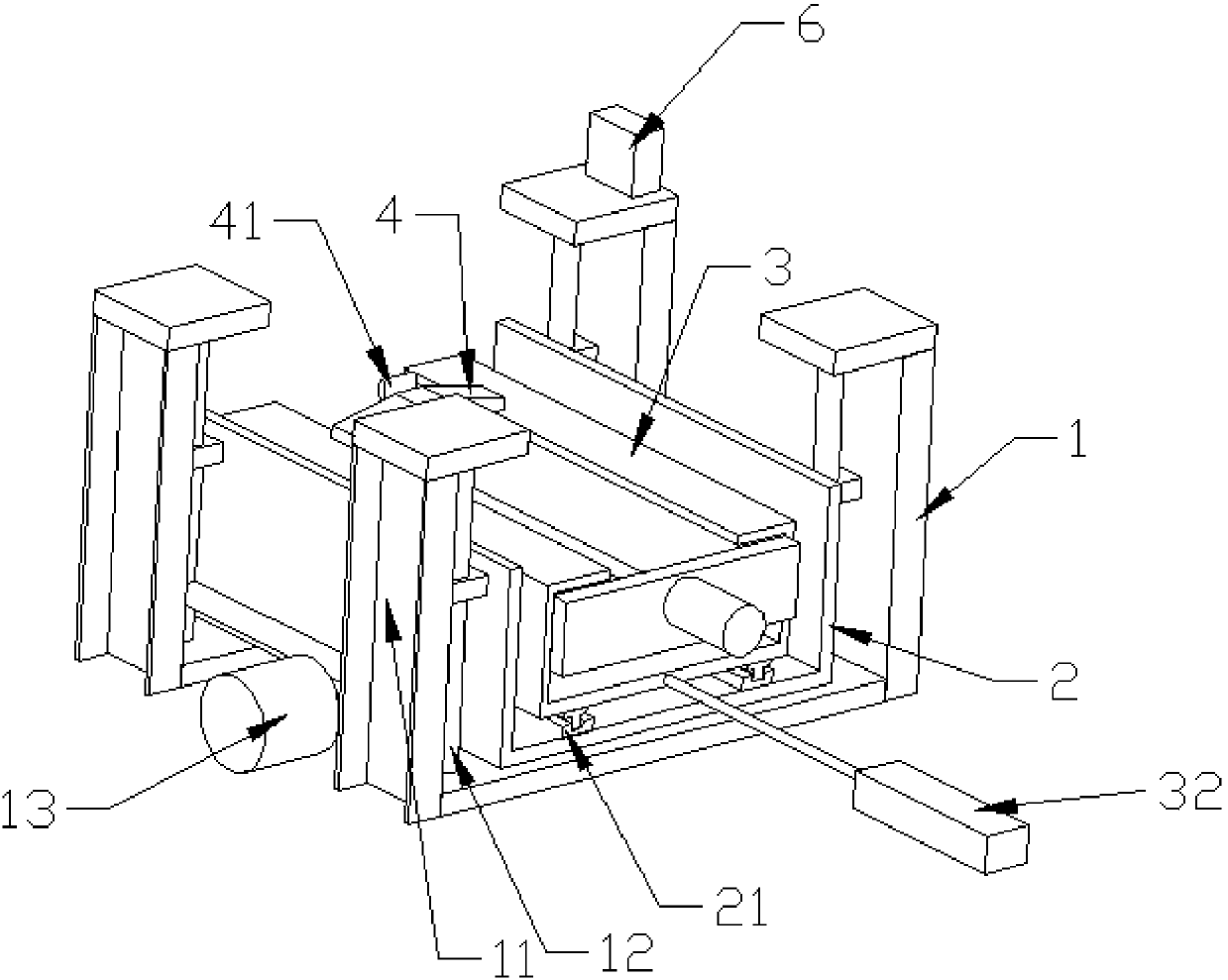
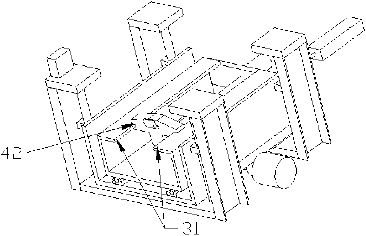
  • Rolling mill auxiliary jig
  • Rolling mill auxiliary jig

Examples


Embodiment Construction

[0018] It should be noted that, in the case of no conflict, the embodiments of the present invention and the features in the embodiments can be combined with each other.

[0019] In describing the present invention, it should be understood that the terms "center", "longitudinal", "transverse", "upper", "lower", "front", "rear", "left", "right", " The orientations or positional relationships indicated by "vertical", "horizontal", "top", "bottom", "inner" and "outer" are based on the orientations or positional relationships shown in the drawings, and are only for the convenience of describing the present invention and Simplified descriptions, rather than indicating or implying that the device or element referred to must have a particular orientation, be constructed and operate in a particular orientation, and thus should not be construed as limiting the invention. In addition, the terms "first", "second", etc. are used for descriptive purposes only, and should not be understood ...


PUM


Abstract

The invention provides a rolling mill auxiliary jig, and belongs to the field of rolling mill roller assembling and disassembling devices. The rolling mill auxiliary jig comprises an assembling and disassembling head which can do up-down vertical movement and front-back horizontal movement. The assembling and disassembling head comprises an upward and backward bend at the front end and a plane structure. The bend is matched with a to-be-assembled/disassembled rolling mill roller. The plane structure is located below the bend, and the rolling mill roller can be conveniently ejected when assembled. The rolling mill roller can be mechanically assembled and disassembled, labor intensity is reduced, and safety and work efficiency are improved.

Description

technical field [0001] The invention belongs to the field of rolling mill equipment, in particular to an auxiliary jig for rolling mills. Background technique [0002] The rolling mill needs regular maintenance. Due to the lack of suitable disassembly and replacement facilities during the maintenance process, the original hoisting equipment is mostly used. However, the rolls of the rolling mill are large in size and heavy in weight. During the maintenance process, a hoisting mechanism needs to be added, and there are many disassembly steps. The process is long, labor-intensive, and safety factor is low; in addition, during the hoisting process, the lifting and lowering of the crane is unstable, and the assembly precision between the roller and the bearing in the archway is very high, so no matter how slow and careful, it often occurs Bearings are damaged by impact, and in severe cases, there will be a dilemma that they cannot be installed or removed, which often delays the t...

Claims


Application Information

Patent Timeline
Patent Type & Authority Applications(China)
IPC IPC(8): B21B31/08
Inventor 宋长毅
Owner TIANJIN YU RUN DE METAL PROD
Why Eureka
Try Eureka