Automatic compensation device of polishing machine

A technology of automatic compensation and compensation device, which is applied to surface polishing machine tools, grinding/polishing equipment, and parts of grinding machine tools, etc. It can solve the problem of unstable contact pressure, inconsistent surface polishing degree of polished workpieces, and affecting workpiece polishing efficiency. and other problems, to achieve the effect of stable contact pressure, consistent polishing degree and improving polishing efficiency

Pending Publication Date: 2018-01-16
潘汉祥
View PDF0 Cites 3 Cited by
  • Summary
  • Abstract
  • Description
  • Claims
  • Application Information

AI Technical Summary

Problems solved by technology

In the existing polishing machine, the workpiece holder can move left and right and up and down, but in practical applications, affected by the polishing process, the contact pressure between the workpiece holder and the polished workpiece is unstable, resulting in inconsistent surface polishing degrees of the polished workpiece , affecting the polishing efficiency of the workpiece

Method used


Image

  • Automatic compensation device of polishing machine
  • Automatic compensation device of polishing machine
  • Automatic compensation device of polishing machine

Examples


Embodiment 1

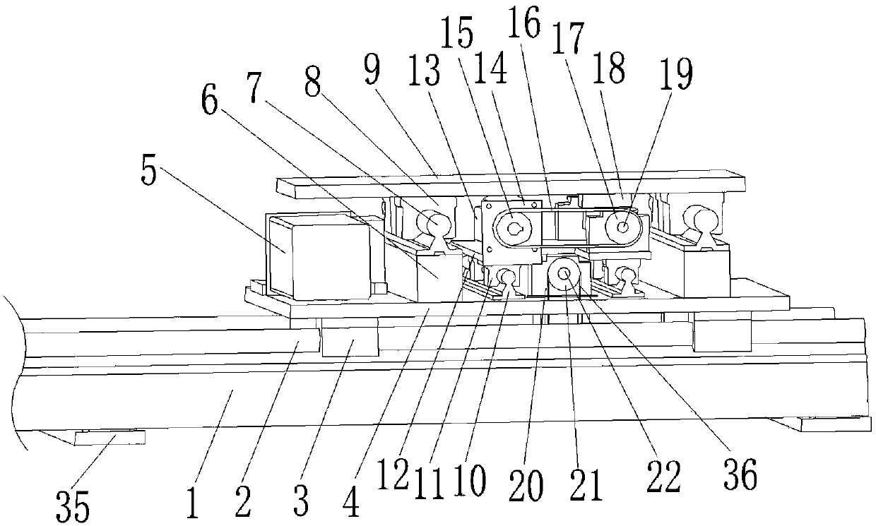
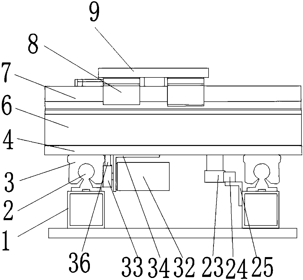
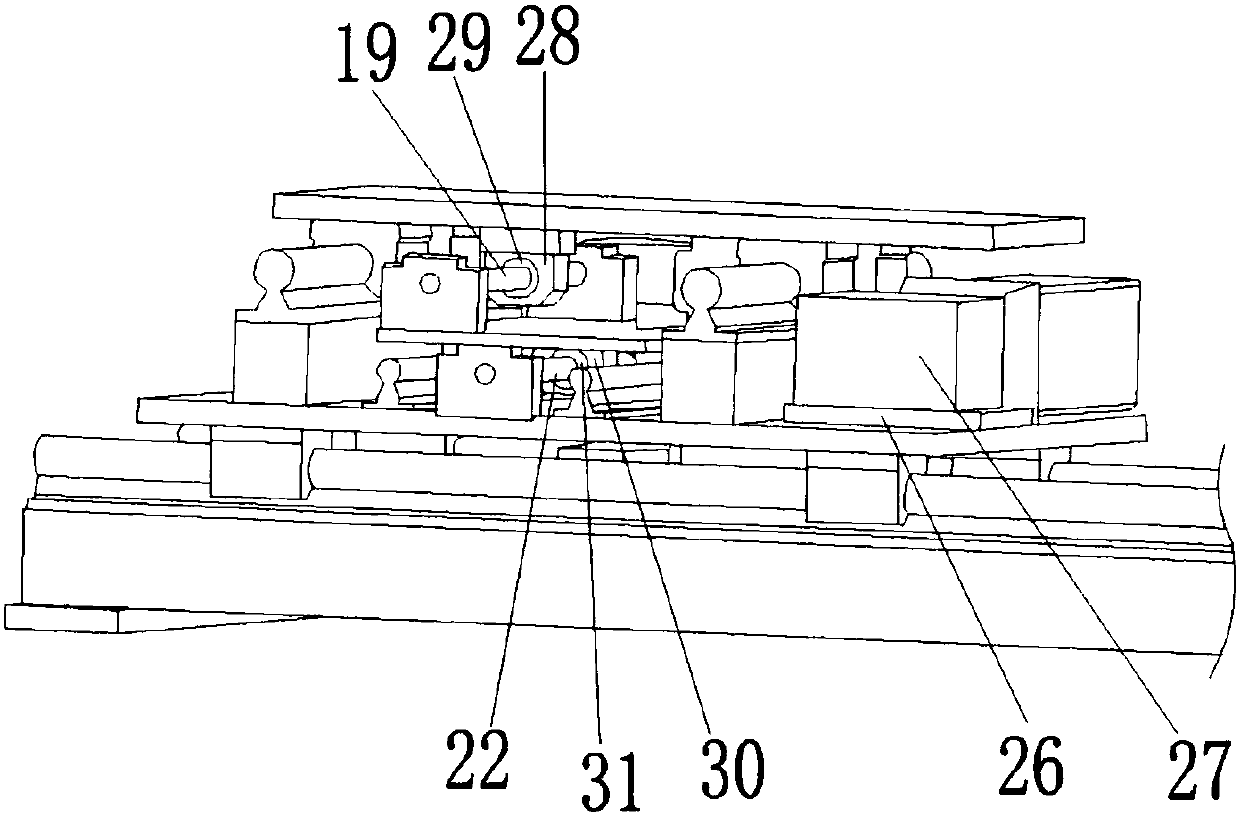
[0028] Figure 1-3 It is a structural schematic diagram of the motor screw type compensation device of the present invention. The motor screw type compensation device includes: a first support plate 35, two first square pipes 1, two first opening guide rails 2, four first opening sliders 3, a first fixing plate 4, and a first motor 5 , two first feet 6, two second opening guide rails 7, four second opening sliders 8, first slide plate 9, two first guide rails 10, four sliders 11, first slider backing plate 12 , the second motor 13, the first motor bracket 14, the first synchronous wheel 15, the first synchronous belt 16, the first tooth synchronous wheel 17, the first connecting block 18, the first screw mandrel 19, four first shaft seats 20 , the second tooth synchronous wheel 21, the second screw mandrel 22, the first gear 23, the first rack 24, the first rack bracket 25, the first gearbox backing plate 26, the first gearbox 27, the first nut seat 28. The first ball nut 29 ...

Embodiment 2

[0037] like Figure 4-6 Shown is a schematic structural view of the counterweight type compensation device of the present invention. The counterweight type compensation device includes: two second square tubes 51, two third opening guide rails 52, four third opening sliders 53, a second sliding plate 54, a fourth motor 55, a second fixing plate 56, Two second feet 57, second slider backing plate 58, two second shaft seats 59, third screw mandrel 60, third ball nut 61, third nut seat 62, two third feet 63, two Second guide rail 64, four rollers 65 (preferably nylon wheels or iron wheels), four roller fixed sleeves 66, counterweight 67, two counterweight supports 68, two connecting wires 69 (preferably steel wires), Two pulleys 70, the third motor support 71, the third synchronous wheel 72, the third tooth synchronous wheel 73, the third synchronous belt 74, the fifth motor 75, the second gearbox backing plate 76, the second gearbox 77, the second gearbox Two rack brackets 78 ...


PUM


Abstract

The invention discloses an automatic compensation device of a polishing machine. The automatic compensation device is a motor lead screw type compensation device or balancing weight type compensationdevice. The automatic compensation device of the polishing machine can ensure that contact pressure between a workpiece clamp and a polished workpiece is stable, the surface polishing degree of the polished workpiece is consistent, and the workpiece polishing efficiency is improved.

Description

technical field [0001] The invention relates to the technical field of polishing equipment, in particular to an automatic compensation device for a polishing machine. Background technique [0002] Polishing machine is a kind of mechanical equipment used for surface rust treatment, oxidation film removal treatment, grinding and smoothing treatment, etc. It is suitable for jewelry crafts, automatic lathe parts, die-casting parts, stamping parts, electronic communication parts, medical parts, aluminum materials Processing of lamp products. In the existing polishing machine, the workpiece holder can move left and right and up and down, but in practical applications, affected by the polishing process, the contact pressure between the workpiece holder and the polished workpiece is unstable, resulting in inconsistent surface polishing degrees of the polished workpiece , affecting the polishing efficiency of the workpiece. [0003] Therefore, there is a need for an automatic compe...

Claims


Application Information

Patent Timeline
IPC IPC(8): B24B41/00B24B41/06B24B29/02
Inventor 潘汉祥
Owner 潘汉祥
Why Eureka
Try Eureka