
Fan blade structure and rotor set thereof

A fan blade and joint technology, which is applied to the components of pumping devices for elastic fluids, non-variable displacement pumps, machines/engines, etc., can solve noise, local thermal stress at the fan blade end, material Fatigue, etc.

Active Publication Date: 2018-01-16
ASIA VITAL COMPONENTS SHENZHEN CO LTD
View PDF6 Cites 0 Cited by
  • Summary
  • Abstract
  • Description
  • Claims
  • Application Information

AI Technical Summary

Problems solved by technology

[0003] However, since the known fan blades on the impeller are flakes, in order to avoid the interference between the blade ends and the inner wall of the chamber at the adjacent two sides, the ends of the fan blades are sharply reduced in thickness. The sharp shape is likely to cause vibration at the end of the blade when it is subjected to the relative force of the fluid, thereby generating operating noise, and the vibration at the end of the blade is likely to cause local thermal stress at the end of the blade and accelerate material fatigue at the end of the blade , affecting the service life of the fan blade

Method used


Image

  • Fan blade structure and rotor set thereof
  • Fan blade structure and rotor set thereof
  • Fan blade structure and rotor set thereof

Examples


Embodiment Construction

[0050] The above-mentioned purpose of the present invention and its structural and functional characteristics will be described based on the preferred embodiments of the accompanying drawings.

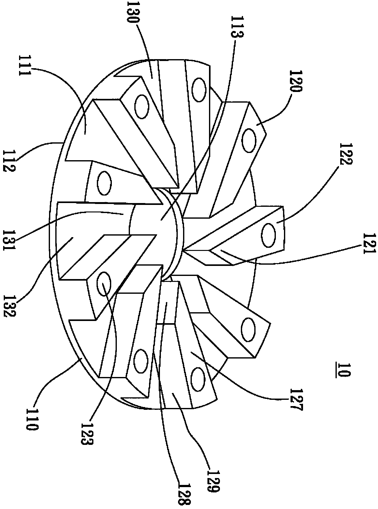
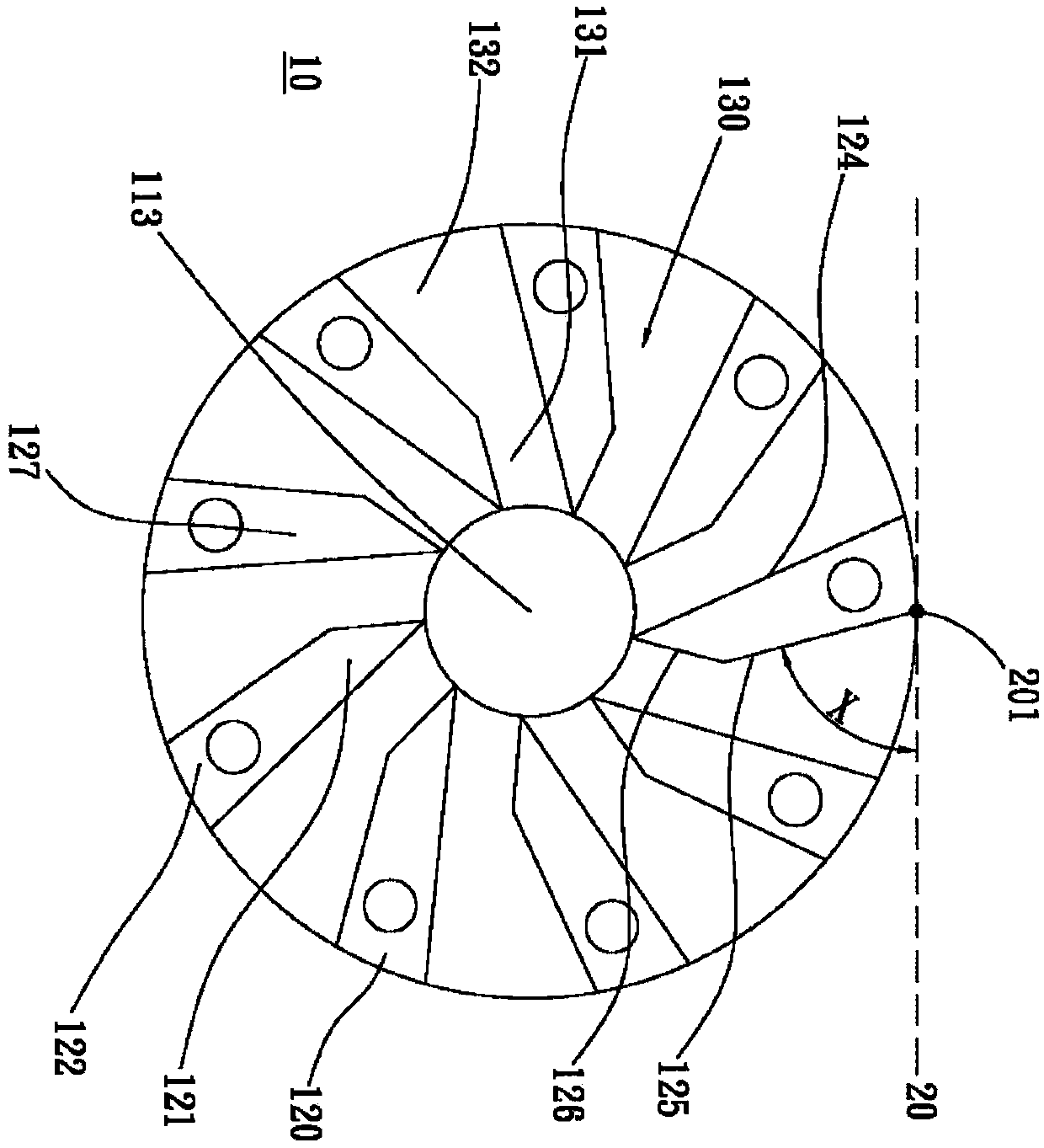
[0051] see figure 1 and figure 2 , is a perspective view and a top view of the first embodiment of the fan blade structure of the present invention. As shown in the figure, the fan blade structure 10 of the present invention includes a body 110. In this embodiment, the fan blade structure 10 is represented as It is applied in a pumping chamber (not shown) of a water-cooled heat dissipation module, but it is not limited thereto. In other embodiments, the fan blade structure 10 can also be applied in other types of pumping chambers. The application of the fan blade structure 10 is not limited by the invention.

[0052] The body 110 has a first side 111, a second side 112 and a first through hole 113, the first side 111 is located on the upper side of the body 110, the second side 112 ...


PUM


Abstract

The invention discloses a fan blade structure and a rotor set thereof. The fan blade structure comprises a body provided with a first through hole communicated with a first side and a second side; a plurality of fan blades are arranged on the first side, each fan blade is provided with a first end and a second end, the first ends are adjacent to or not adjacent to the edges of the first through hole, the fan blades are provided with a plurality of binding portions, each fan blade is provided with a first edge, a second edge and a third edge, the first and second edges extend from the second ends to the first through hole, the third edges are connected to the first and second edges at the first ends, a virtual line is tangent to the portions, making contact with the edge of the body, of thesecond edges so as to form an included angle with the second edge, and a channel is defined between every two adjacent fan blades. Due to the design, the effects of lowering fan blade noise and prolonging the service life of the fan blades can be effectively achieved.

Description

【Technical field】 [0001] The invention relates to a fan blade structure and its rotor group, in particular to a fan blade structure and its rotor group which can reduce noise and increase service life. 【Background technique】 [0002] According to, the known pump has a chamber, and the chamber is provided with two through holes, and the chamber communicates with the outside world through the two through holes, so that a fluid enters or exits the chamber through the two through holes, An impeller is arranged in the rotating component of the chamber, and the centrifugal force and pressure change generated by the rotation of the impeller can suck the fluid into the chamber through one of the through holes, and discharge the fluid out of the chamber through the other through hole. In this way, the purpose of pumping fluid can be achieved. [0003] However, since the known fan blades on the impeller are flakes, in order to avoid the interference between the blade ends and the inn...

Claims


Application Information

Patent Timeline
Patent Type & Authority Applications(China)
IPC IPC(8): F04D29/28F04D29/58F04D29/66
Inventor 邱俊春殷建武
Owner ASIA VITAL COMPONENTS SHENZHEN CO LTD
Learn More