
Power distribution network fault positioning and boundary defining method based on fault indicator

A fault indicator and fault location technology, applied in the fault location and other directions, can solve the problems of weak fault signal, fault detection, line selection, difficult positioning, small fault current, etc., to achieve the effect of a wide range of applications

Inactive Publication Date: 2018-01-16
邓永忠
View PDF0 Cites 6 Cited by
  • Summary
  • Abstract
  • Description
  • Claims
  • Application Information

AI Technical Summary

Problems solved by technology

[0003] The technical problem to be solved by the present invention is that when a small-current single-phase grounding fault occurs in the system, the fault current is very small and the fault signal is weak, which makes fault detection, line selection, and positioning very difficult. The purpose is to provide a fault indicator for the distribution network The method of realizing fault location and demarcation solves the problem that when a small current single-phase ground fault occurs in the system, the fault current is very small and the fault signal is weak, which makes fault detection, line selection, and location very difficult

Method used


Image

  • Power distribution network fault positioning and boundary defining method based on fault indicator
  • Power distribution network fault positioning and boundary defining method based on fault indicator
  • Power distribution network fault positioning and boundary defining method based on fault indicator

Examples


Embodiment 1

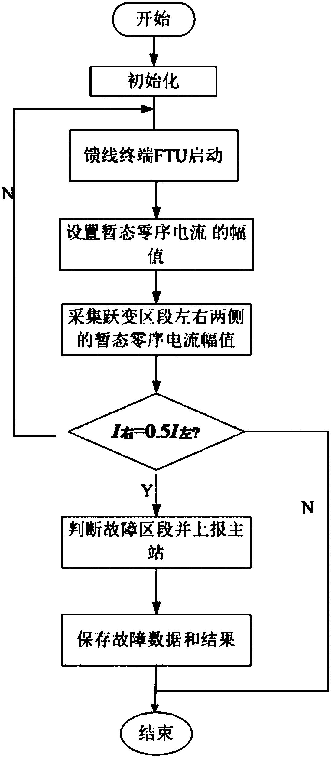
[0024] The method for realizing fault location and demarcation of a distribution network through a fault indicator in the present invention comprises the following steps:

[0025] A: Set the threshold value I for starting the feeder terminal device st ;

[0026] B: Collect the transient zero-sequence current of each detection point at the exit of the busbar and the threshold value I for starting the feeder terminal device st Make a comparison to judge whether the start-up conditions of the feeder terminal device are met;

[0027] C: If the conditions are met, the feeder terminal device starts, records the fault information and enters step D for the next step of processing and calculation;

[0028] D: Calculate the amplitude of transient zero-sequence current at each detection point on each line, and select at least three lines with the largest amplitude of transient zero-sequence current;

[0029] E: According to the variation of transient zero-sequence current amplitude of...


PUM


Abstract

The invention discloses a power distribution network fault positioning and boundary defining method based on a fault indicator. An aim of the invention is to provide the power distribution network fault positioning and boundary defining method based on the fault indicator. The method can be used for solving problems of difficult fault detecting, line selecting and positioning caused due to small fault currents and weak fault signals when small current single phase grounding faults occur in a system. The method comprises the following steps: transient zero sequence currents of all detection points on all lines at a bus exit opening are collected; when the faults occur in the lines, the transient zero sequence currents change abruptly; amplitudes of the transient zero sequence currents of all the detection points on all the lines are calculated, at least three lines with maximum amplitudes of the transient zero sequence currents are selected, and the small current grounding faults can bepositioned according to change of the amplitudes of the transient zero sequence currents of all the detection points on the lines selected in step D. The method is advantageous in that for lines without small current line selecting devices in a station, on-line fault monitoring can be realized, and fault positions can be found timely.

Description

technical field [0001] The invention relates to a fault location method, in particular to a method for a distribution network to realize fault location and boundary through a fault indicator. Background technique [0002] By 2020, the level of intelligent construction and application in central cities (districts) will be greatly improved, the reliability rate of power supply will reach 99.99%, the average annual power outage time of users will not exceed 1 hour, and the quality of power supply will reach the international advanced level; power supply capacity and power supply safety level in urban areas Significantly improved, the power supply reliability rate has reached more than 99.88%, and the average annual power outage time of users does not exceed 10 hours, ensuring the rapid economic and social development of the region; rural and remote areas have comprehensively solved the problem of weak power grids, basically eliminated long-term "low voltage", and distributed tra...

Claims


Application Information

Patent Timeline
Patent Type & Authority Applications(China)
IPC IPC(8): G01R31/08
Inventor 邓永忠
Owner 邓永忠
Learn More