Solid beam and circular beam shifting device

A technology of annular beam and conversion device, applied in optics, optical components, instruments, etc., can solve the problems of poor effect of stimulated Raman of hollow spot, and achieve the effects of low cost, easy price and convenient use.

Inactive Publication Date: 2018-01-16
DALIAN INST OF CHEM PHYSICS CHINESE ACAD OF SCI
View PDF5 Cites 18 Cited by
  • Summary
  • Abstract
  • Description
  • Claims
  • Application Information

AI Technical Summary

Problems solved by technology

The unstable cavity is usually a hollow beam output, but the stimulated Raman effect of the hollow spot is much worse than that of the solid spot

Method used


Image

  • Solid beam and circular beam shifting device
  • Solid beam and circular beam shifting device
  • Solid beam and circular beam shifting device

Examples


Embodiment Construction

[0022] In the following, the conversion from a solid beam to a hollow beam will be mainly introduced in conjunction with the accompanying drawings, and the structure and principle of the present invention will be further described in detail.

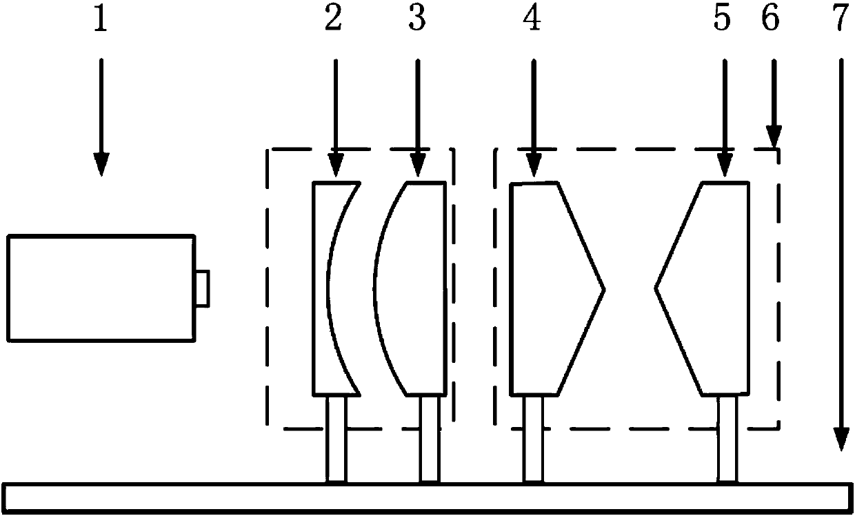
[0023] The present invention produces an adjustable annular light beam device, such as figure 1 Shown, comprise optical rail, laser 1, plano-concave lens 2, plano-convex lens 3, conical lens 4, conical lens 5 and optical rail 7, plano-concave lens 2, plano-convex lens 3 are fixed on optical rail 7, conical The bases of the lens 4 and the conical lens 5 are respectively fixed on the electric translation stage, and the translation stage is fixed on the optical rail 7, and the placement positions are as follows: figure 1 shown.

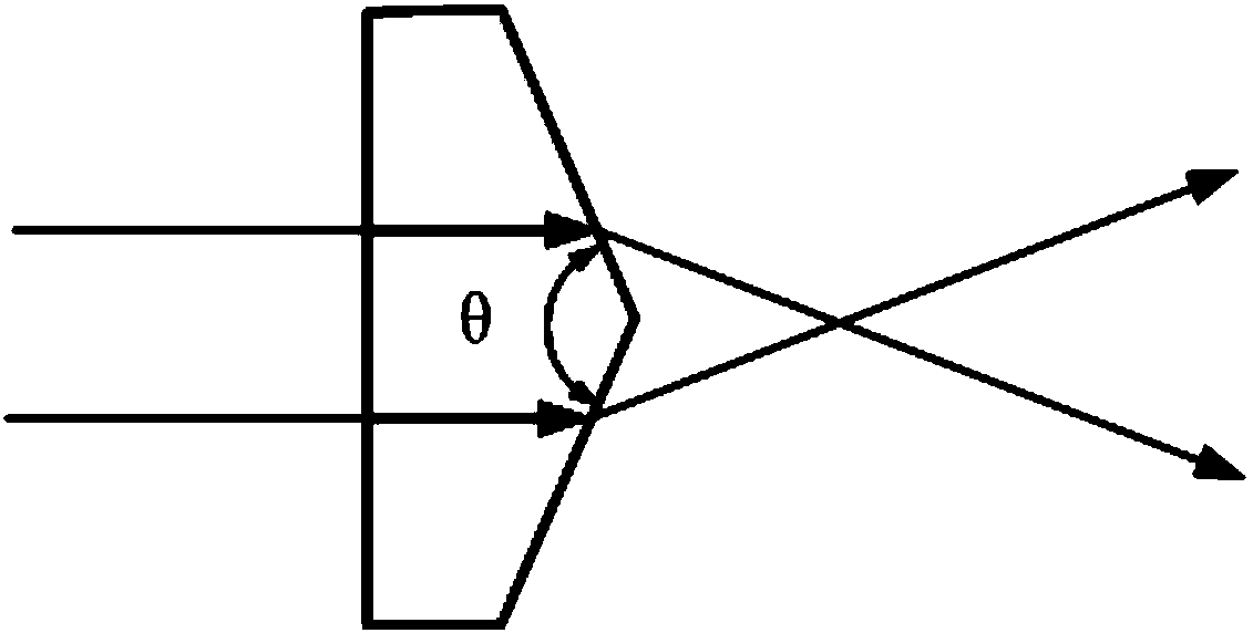
[0024] When working from a solid beam to a hollow beam, turn on the laser, and the laser beam generated by the laser is expanded and collimated by the plano-concave lens 1 and the plano-convex lens 2, and then t...


PUM


Abstract

The invention provides a solid beam and circular beam shifting device based on conical lenses, which comprises a laser 1, a beam expanding and collimating system formed by a plano-concave lens 2 and aplano-convex lens 3, a conical lens 4 and a conical lens 5, wherein the first end surface of the conical lens 4 is a plane and the second end surface is a conical surface, and the conical lens 4 andthe conical lens 5 have the same feature parameters. The distance between the conical lens group is adjusted by an electric translation platform. The obstruction ratio of the circular beam is decidedby magnification of the beam expanding system. According to the solid beam and circular beam shifting device, the optical path is simply designed, practicability and convenience are facilitated, energy loss is little, the optical interfaces are few, beam aberration is little influenced, the radius of the beam is adjustable, and demands on shifting between the solid beam and different sizes of circular beams can be met.

Description

technical field [0001] A conversion device for a solid beam and a ring beam, using a system composed of two conical mirrors with the same configuration, a plano-convex lens and a plano-concave lens, to realize the transformation from a solid circular beam to a ring beam or from a ring beam to a circular beam transform. The device can realize the transformation from the same solid circular light spot to the annular light spot with different obscuration ratios, and can also realize the arbitrary transformation between the annular light spots with different obscuration ratios. Background technique [0002] At present, the most common solid-state YAG lasers, fiber lasers, He-Ne lasers and most dye lasers output solid circular spot. The actual application is usually varied. For example, if the Cassegrain system is used to transmit the beam to the far field, it is necessary to block a relatively large ring-shaped spot. In addition, certain detection techniques, such as USED-CAR...

Claims


Application Information

Patent Timeline
Patent Type & Authority Applications(China)
IPC IPC(8): G02B27/09G02B26/00
Inventor 王颜超郭敬为王鹏远刘金波
Owner DALIAN INST OF CHEM PHYSICS CHINESE ACAD OF SCI
Why Eureka
Try Eureka