
Brushless signal direct current switch

A DC switch and signal technology, which is applied in the direction of electric switches, electrical components, circuits, etc., can solve the problems of shortening the service life of switches, failure of opening and closing circuits, and easy entry of dust into the housing, so as to prolong the service life and prevent failures.

Active Publication Date: 2018-01-16
SUZHOU HUAZHIJIE TELECOM +1
View PDF8 Cites 1 Cited by
  • Summary
  • Abstract
  • Description
  • Claims
  • Application Information

AI Technical Summary

Problems solved by technology

[0002] Brushless signal switches are widely used in various brushless electric tools. Since brushless signal switches are weak current control switches, the internal switching circuits are arranged closely and are easily affected by dust. When the switching circuits in the switch accumulate In the working environment of electric tools, due to the poor sealing performance of traditional brushless signal switches, dust can easily enter the housing and affect the normal on-off of the circuit, especially with For the brushless signal DC switch with reversing function, since the housing is provided with a swing hole for the handle, dust can easily enter the housing through the swing hole of the handle and attach to the switching circuit, resulting in failure of the switching circuit and shortening the switch. service life

Method used


Image

  • Brushless signal direct current switch
  • Brushless signal direct current switch
  • Brushless signal direct current switch

Examples


Embodiment Construction

[0031] Specific embodiments of the present invention will be described in detail below in conjunction with the accompanying drawings.

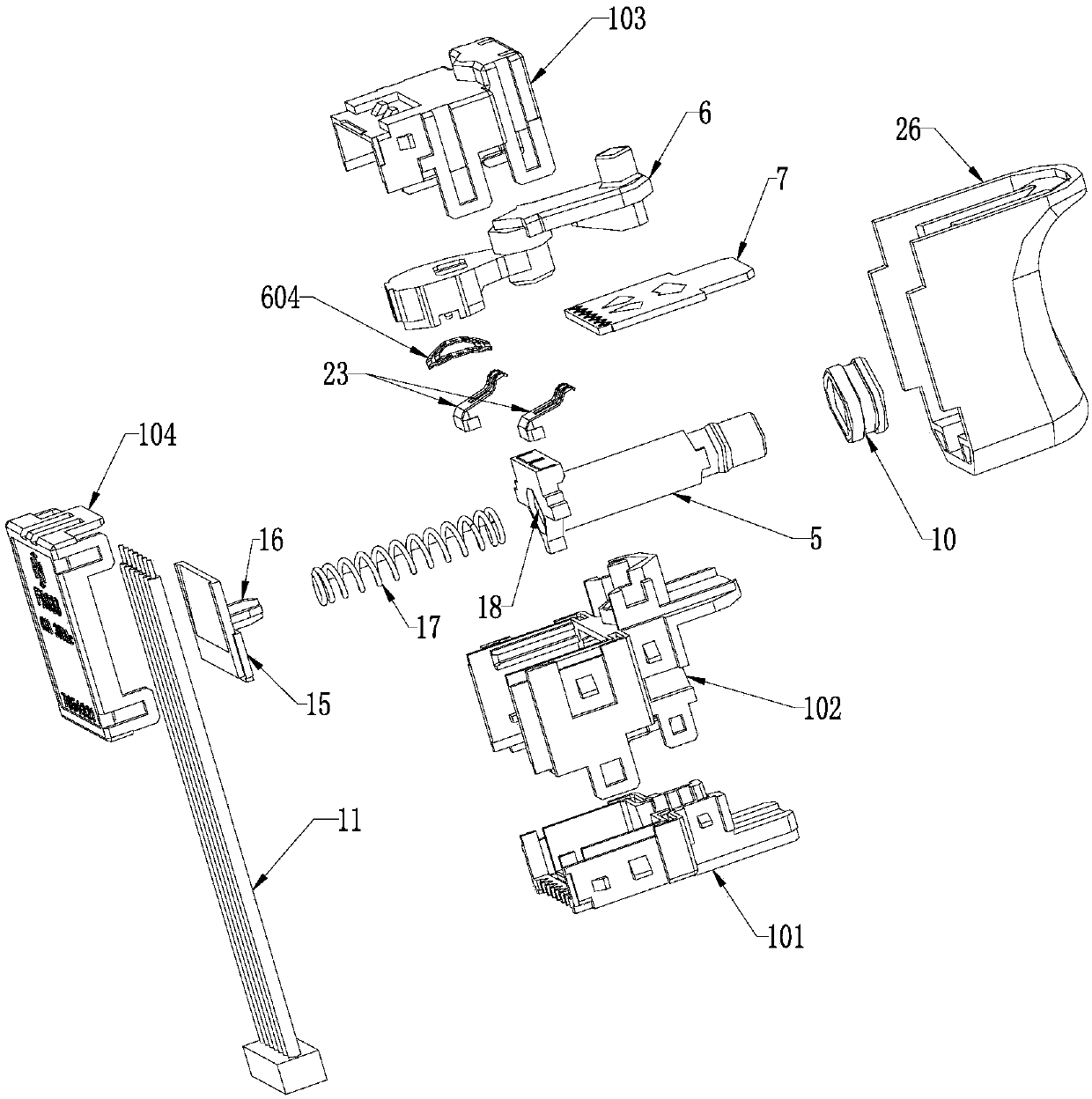
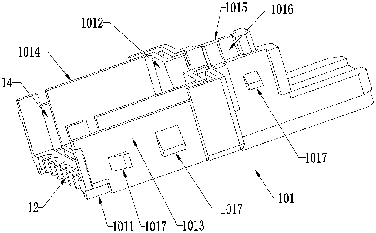
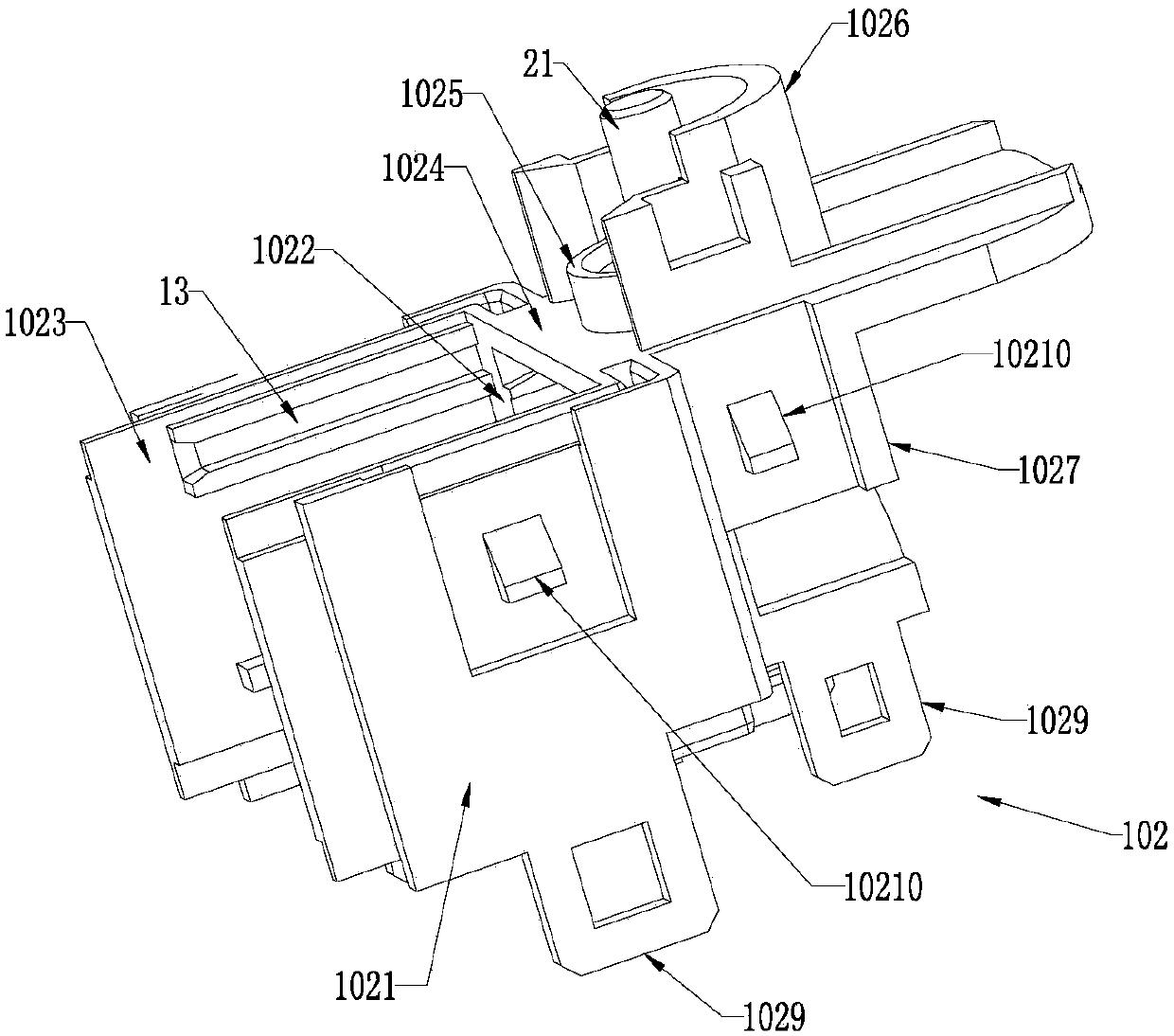
[0032] Such as figure 1 , Figure 7 The shown brushless signal DC switch includes a housing 1, which is provided with a push rod installation hole 2, a handle swing hole 3, and a signal line connection hole 4, and the push rod installation hole 2 is inserted with a The push rod 5, the reversing handle 6 is arranged in the swing hole 3 of the handle, the PCB board 7 is arranged in the housing 1, an opening and closing circuit is arranged on one side of the PCB board, and a reversing circuit is arranged on the other side, and its end The part is provided with connecting terminals, the push rod 5 is used to control the opening and closing of the switching circuit, the reversing handle 6 is used to control the reversing of the reversing circuit, and the PCB board 7 divides the inside of the housing 1 into The reversing chamber 8 and the opening ...


PUM


Abstract

The invention discloses a brushless signal direct current switch. The brushless signal direct current switch comprises a shell, a push rod and a shifting handle; a PCB is arranged in the shell; an opening-closing circuit is arranged on one side of the PCB while a reversing circuit is arranged on the other side, and a terminal is arranged on the end part; the push rod is used for controlling opening and closing of the opening-closing circuit; the reversing shifting handle is used for controlling reversing of the reversing circuit; the interior of the shell is divided by the PCB into a reversingcavity and an opening-closing cavity which are isolated mutually; the push rod is inserted in the opening-closing cavity, and the space between the push rod and the shell is sealed by an elastic dustproof ring; the reversing shifting handle is inserted into the reversing cavity, the opening-closing circuit on the PCB faces the opening-closing cavity, and the reversing circuit faces the reversingcavity; a signal line connecting hole is formed in the bottom of the shell; and the signal line connecting hole is tightly matched with a signal line. The interior of the shell is divided by the PCB into the reversing cavity and the opening-closing cavity which are isolated mutually; and the space between the push rod and the shell is sealed by the elastic dustproof ring, so that the brushless signal direct current switch is simple in structure and capable of effectively blocking dust accumulation on the open-closing circuit.

Description

technical field [0001] The invention relates to a switch, in particular to a brushless signal DC switch. Background technique [0002] Brushless signal switches are widely used in various brushless electric tools. Since brushless signal switches are weak current control switches, the internal switching circuits are arranged closely and are easily affected by dust. When the switching circuits in the switch accumulate In the working environment of electric tools, due to the poor sealing performance of traditional brushless signal switches, dust can easily enter the housing and affect the normal on-off of the circuit, especially with For the brushless signal DC switch with reversing function, since the housing is provided with a swing hole for the handle, dust can easily enter the housing through the swing hole of the handle and attach to the switching circuit, resulting in failure of the switching circuit and shortening the switch. service life. Contents of the invention ...

Claims


Application Information

Patent Timeline
Patent Type & Authority Applications(China)
IPC IPC(8): H01H9/04H01H9/02
Inventor 周建辉
Owner SUZHOU HUAZHIJIE TELECOM
Learn More