Circuit breaker connecting apparatus

A connection device and circuit breaker technology, applied in the direction of protective switch terminals/connection, etc., can solve the problems of inconvenient wiring, etc., and achieve the effect of simple and safe wiring, uniform arrangement, and neat wiring

Inactive Publication Date: 2018-01-16
YUEQING GAOKE ENVIRONMENTAL CO LTD
View PDF8 Cites 3 Cited by
  • Summary
  • Abstract
  • Description
  • Claims
  • Application Information

AI Technical Summary

Problems solved by technology

[0004] Therefore, the technical problem to be solved by the present invention is to overcome the defect of inconvenient wiring when multiple circuit breakers with different numbers of poles are simultaneously con

Method used


Image

  • Circuit breaker connecting apparatus
  • Circuit breaker connecting apparatus
  • Circuit breaker connecting apparatus

Examples


Embodiment 1

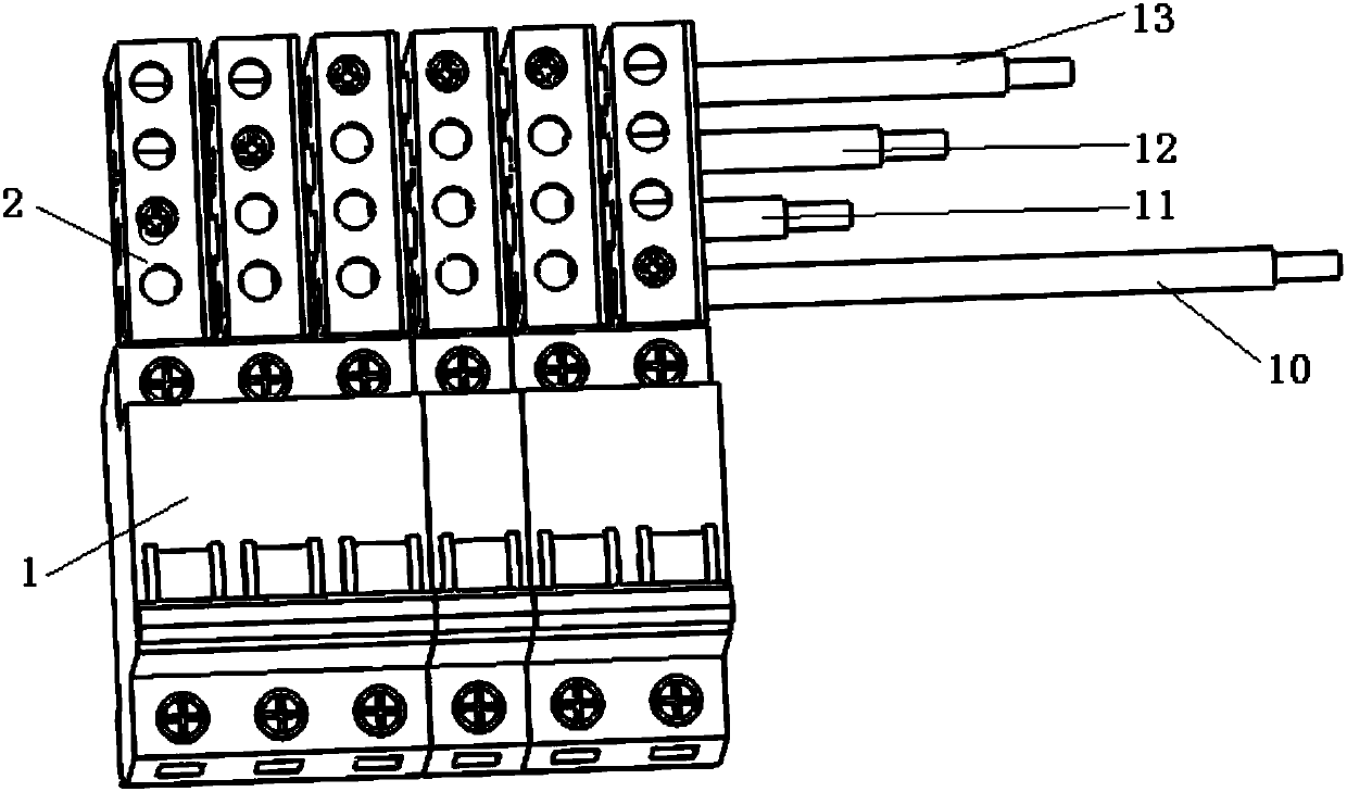
[0043] Such as Figure 1-3A specific implementation of a circuit breaker connection device shown includes several connection units 2 arranged side by side, and each connection unit 2 includes: a body, the body is provided with a number of first through holes 3, each The first through hole 3 is suitable for different conductors to pass through; the conductive structure is arranged on the body, including a first end 4 electrically connected to the corresponding connection terminal of the circuit breaker 1, and passes through one of the first ends 4. The second end of the electrical connection of the conductor in a through hole 3; the first through hole 3 at the same position on the connecting unit 2 arranged side by side cooperates to form a conductor channel for the conductor to pass through. When in use, several connection units 2 are arranged side by side and connected to the circuit breaker 1, and different conductors pass through the conductor channels formed by the first t...

Embodiment 2

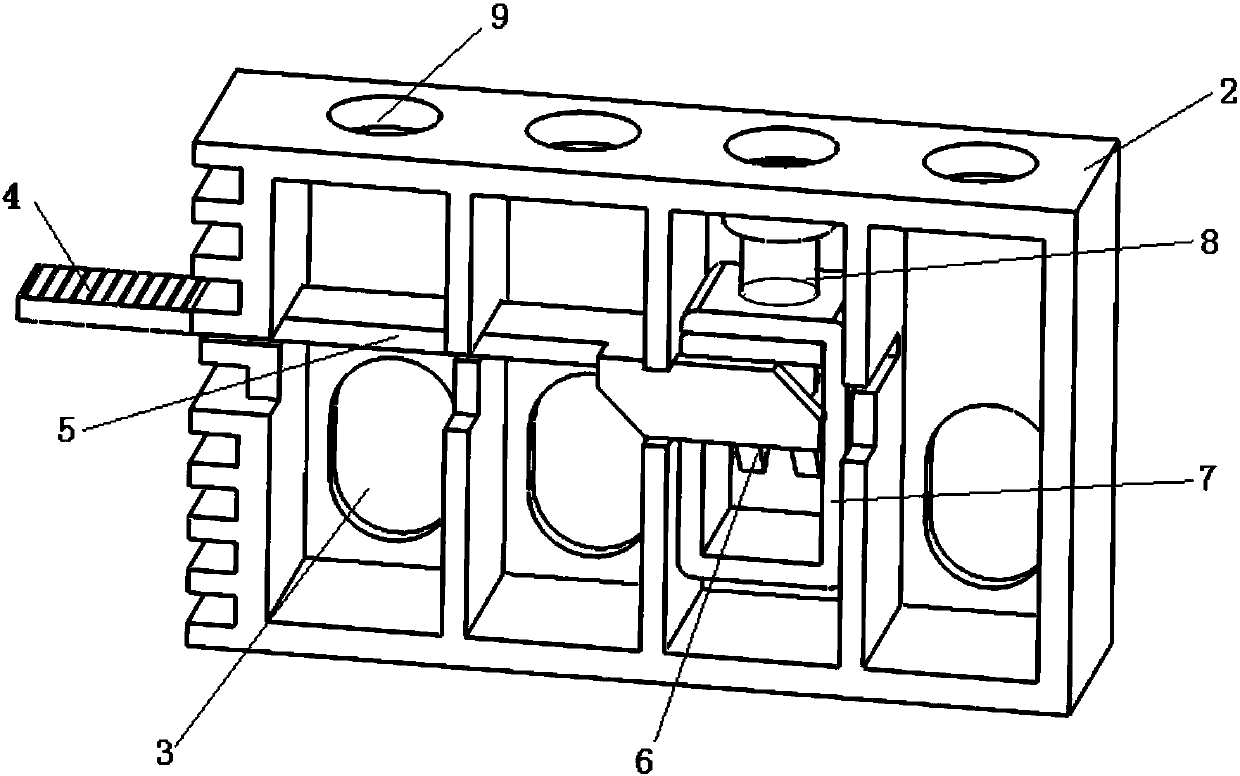
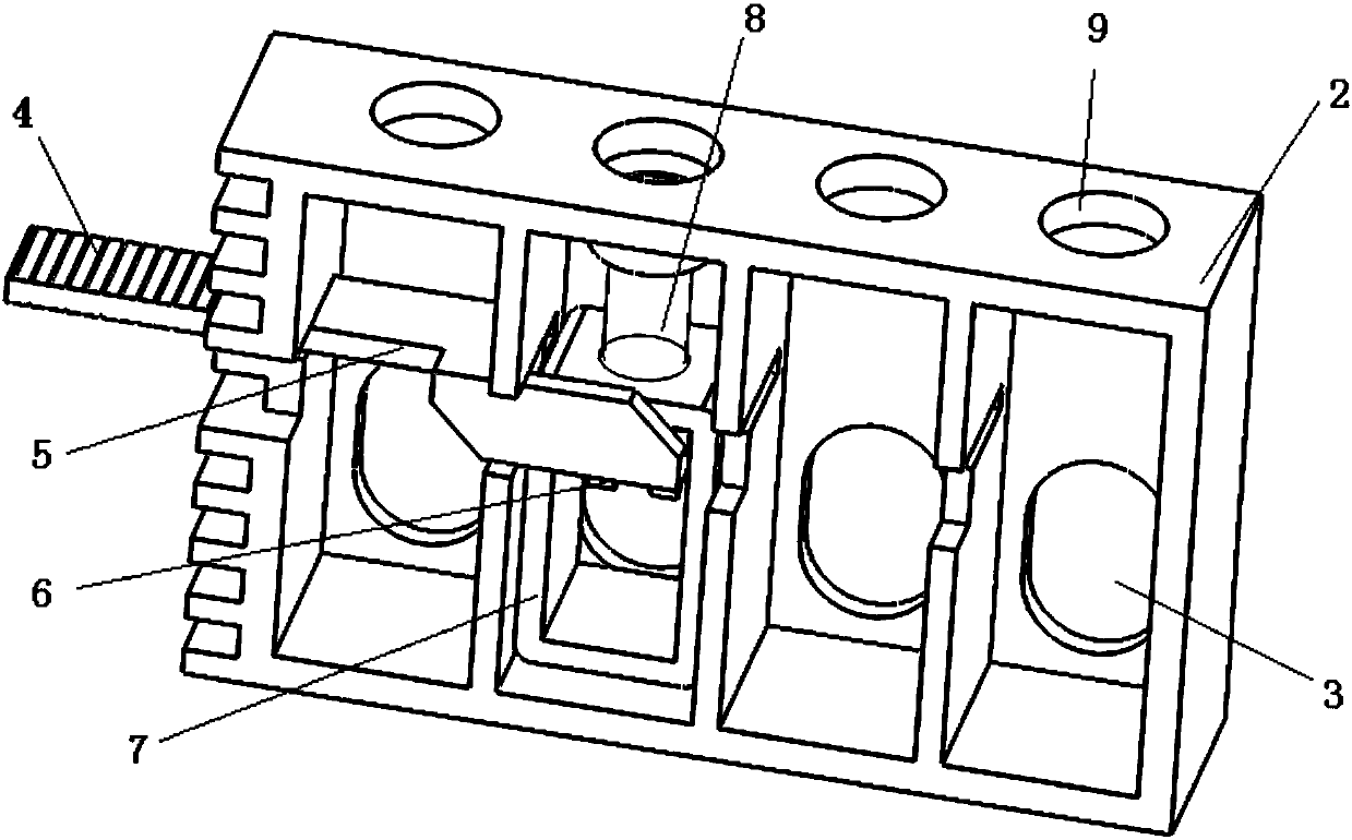
[0049] The difference between this embodiment and the above-mentioned embodiments is that the conductor is an insulated wire, and the conductive structure includes a puncture screw that enters the second through hole 9 and punctures the insulation, and is connected with the puncture screw and A conductive member 5 conducting with the first end. When in use, the puncture screw enters through the second through hole 9, and the tip of the screw head punctures the insulation of the wire and communicates with the conductor.

Embodiment 3

[0051] The difference between this embodiment and the above two embodiments is that the conductor is a metal wire, and the conductive structure includes a screw connected to the metal wire and a conductive member 5 connected to the screw, and the screw forms a The second end, the end of the conductive member 5 extending to the outside of the device body forms the first end 4 . The screw enters through the second through hole 9, and the head of the screw contacts the metal wire and communicates with the wire, and transmits the current to the first end.


PUM


Abstract

The invention provides a circuit breaker connecting apparatus. The circuit breaker connecting apparatus comprises a plurality of connecting units arranged in parallel; each connecting unit comprises abody, a conductive structure and a conductor channel, wherein a plurality of first through holes are formed in the body; the respective first though holes are suitable for allowing different conductors to pass through; the conductive structure is arranged on the body, and the conductive structure comprises a first end electrically connected with a corresponding connecting terminal of the circuitbreaker, and a second end electrically connected with the corresponding conductor which passes through one of the first through holes; and the first through holes formed in the same positions of the connecting units in parallel form the conductor channel for allowing the conductors to pass through. When the circuit breaker connecting apparatus is in use, the multiple connecting units are connectedto the circuit breaker in parallel; by virtue of a side wire inlet mode, different conductors pass through the conductor channel formed by the corresponding first through holes in each connecting unit; all the conductors are all uniformly distributed in the connecting apparatus, so that tidy wiring is realized; and a condition that the conductor is bent and shifted through a direct front surfacewire inlet and wire outlet mode adopted at present is not needed, so that the wiring mode is simple and safe.

Description

technical field [0001] The invention relates to the technical field of electrical engineering components, in particular to a circuit breaker connection device. Background technique [0002] A circuit breaker refers to a switching device that can close, carry and break current under normal circuit conditions and can close, carry and break current under abnormal circuit conditions within a specified time. Circuit breakers can be used to distribute electric energy, start asynchronous motors infrequently, protect power lines and motors, and automatically cut off the circuit when they are severely overloaded, short-circuited, or under-voltage. Its function is equivalent to a fuse-type switch. Combination with overheating and underheating relays, etc. Moreover, there is generally no need to change parts after breaking the fault current. At present, it has been widely used. [0003] When the existing circuit breaker is connected to the power supply, it is generally connected by ...

Claims


Application Information

Patent Timeline
IPC IPC(8): H01H71/08
Inventor 刘响荣李靖
Owner YUEQING GAOKE ENVIRONMENTAL CO LTD
Why Eureka
Try Eureka