Bar chair with rotation function

A technology of rotating function and bar chair, which is applied in the field of bar chairs with rotating function, can solve the problems of uncontrollable rotation speed of stools and chairs, troublesome installation and potential safety hazards, etc., so as to improve the safety of use and the accuracy of installation , the effect of easy installation

Inactive Publication Date: 2018-01-19
徐春晖
6 Cites 0 Cited by

AI-Extracted Technical Summary

Problems solved by technology

However, the rotation of existing bar chairs is mainly realized by setting a rotating shaft, and the installation process is relatively troublesome; and when rotating in this way, the rotation of the chair is relati...

Abstract

The invention discloses a bar chair with rotation function. The bar chair comprises a chair supporting wood rack (1) with a circular truncated cone structure, the middle part of the chair supporting wood rack (1) is provided with a connecting circular ring (2), a rotary stool surface (3) is arranged on the chair supporting wood rack (1), and a cushion (4) is arranged on the rotary stool surface (3); the chair supporting wood rack (1) comprises four supporting legs (5) which are arranged in a circular truncated cone structure, a support plate (6) is arranged on the supporting legs (5), the support plate (6) is provided with screwed holes (7), and a non-skid mat is arranged below the supporting legs (5). The product has characteristics of installation convenience and usage security improvement.

Application Domain

StoolsAdjustable chairs

Technology Topic

Rotation functionCushion +1

Image

  • Bar chair with rotation function
  • Bar chair with rotation function
  • Bar chair with rotation function

Examples

  • Experimental program(1)

Example Embodiment

[0013] The present invention will be further described below in conjunction with the accompanying drawings and embodiments, but not as a basis for limiting the present invention.
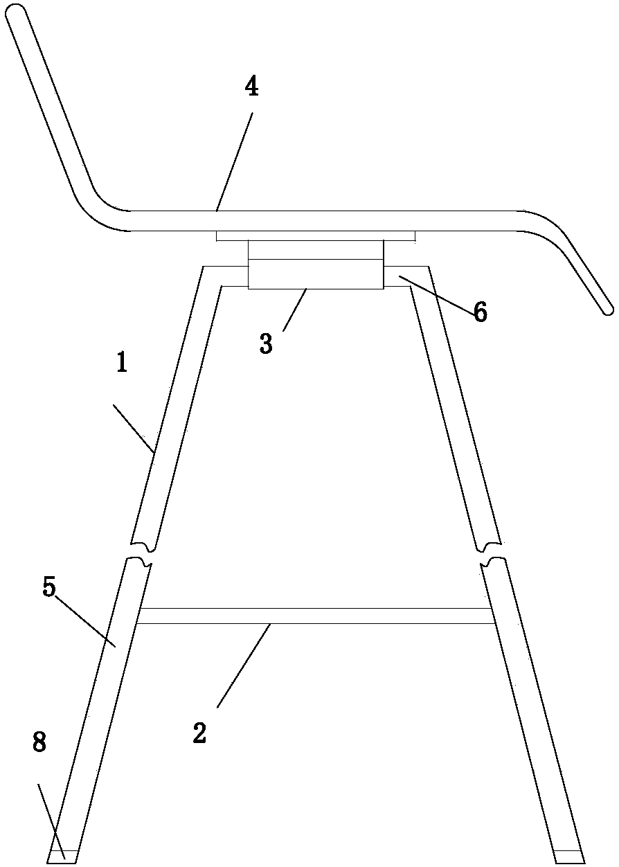
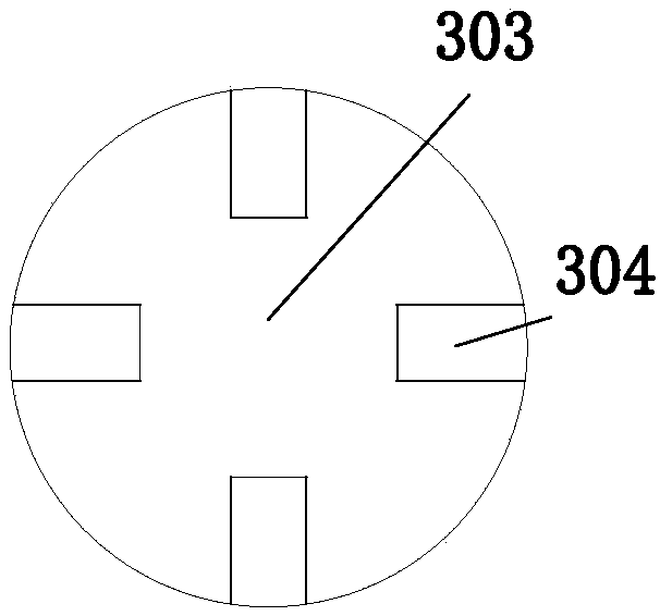
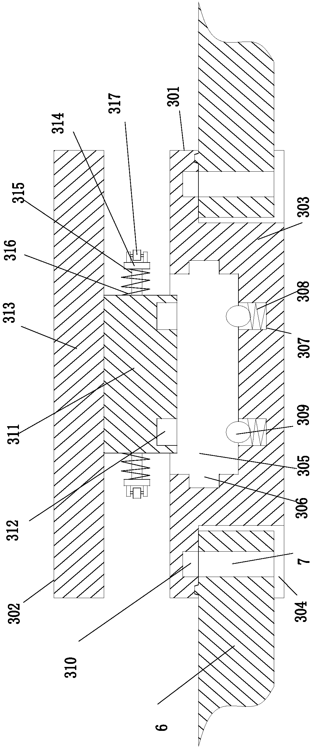
[0014] Example. A bar chair with swivel function, constituted as Figure 1 to Figure 3 As shown, it includes a chair support frame 1 with a round platform structure, a connecting ring 2 is provided in the middle of the chair support frame 1, a rotating stool surface 3 is provided above the chair support frame 2, and a seat cushion 4 is provided above the rotating stool surface 3; The chair support wooden frame 1 includes 4 legs 5 arranged in a circular truncated structure, the upper end of the legs 5 is provided with a support plate 6, the support plate 6 is provided with a threaded hole 7, and the lower end of the support leg 5 is provided with a non-slip pad 8 . The support plate 6 is also provided with a positioning inclined block, and the fixing groove 304 is also provided with a groove corresponding to the positioning inclined block.
[0015] The rotating stool surface 3 includes a fixed seat 301 fixed to the chair support wooden frame 1, and a rotating seat 302 is arranged above the fixed seat 301; 6 matching fixing groove 304, a circular groove 305 is provided above the seat body 303, an annular clamping groove 306 is provided on the inner wall of the circular groove 305, and a plurality of annularly arranged mounting holes 307 are provided at the bottom of the circular groove 305, and the mounting holes A spring 308 and a positioning ball 309 are sequentially arranged in the 307 .
[0016] The fixing slot 304 is provided with a fixing hole 310 corresponding to the threaded hole 7 .
[0017] The rotating seat 302 includes a rotating cylinder 311 matched with the circular groove 305, a positioning hole 312 corresponding to the mounting hole 307 is provided at the bottom of the rotating cylinder 311, and a mounting plate 313 is provided above the rotating cylinder 311; The outer wall of 311 is provided with two symmetrically arranged convex strips 314, and the convex strips 314 are matched with the annular slot 306; a telescopic rod 315 is arranged between the inner wall of the convex strip 314 and the outer wall of the rotating cylinder 311, and the telescopic rod 315 is covered A compression spring 316 is provided; a roller 317 is provided on the outer wall of the annular raised strip 314 .
[0018] The working process of the present invention: by manually compressing the convex strip and the roller, the rotating cylinder enters the circular groove. After the roller reaches the annular groove, it elongates under the action of the spring force, and the roller contacts the annular groove. The installation hole and The positioning holes are matched, and the positioning is carried out by positioning balls. During the rotation process, the rotating seat is rotated, and the roller moves along the annular slot. At the same time, the lower end surface of the rotating cylinder contacts the positioning ball, and the positioning ball is compressed, so that the positioning ball drives the compression spring to contract. When the next positioning hole appears, the positioning The ball resets under the action of the spring force to realize positioning and limit.

PUM

no PUM

Description & Claims & Application Information

We can also present the details of the Description, Claims and Application information to help users get a comprehensive understanding of the technical details of the patent, such as background art, summary of invention, brief description of drawings, description of embodiments, and other original content. On the other hand, users can also determine the specific scope of protection of the technology through the list of claims; as well as understand the changes in the life cycle of the technology with the presentation of the patent timeline. Login to view more.

Similar technology patents

Supercritical water jet cleaning equipment

Owner:INST OF MICROELECTRONICS CHINESE ACAD OF SCI

Method and device for video monitoring

ActiveCN103391422AImprove safety performance
Owner:CHINA MOBILE COMM GRP CO LTD

Classification and recommendation of technical efficacy words

  • Improve safety performance
  • Easy to install

Electric monocycle

InactiveCN104760644AImprove safety performanceAdaptable to road conditions
Owner:UNIV OF SHANGHAI FOR SCI & TECH

Near field communication terminal with security mechanism

ActiveCN102215053AImprove safety performancePrevent false charges
Owner:HUIZHOU TCL MOBILE COMM CO LTD

Network system for realizing integrated security services

ActiveCN101771619AImprove safety performance
Owner:NO 30 INST OF CHINA ELECTRONIC TECH GRP CORP

Balancing device and crane with same

InactiveCN102020211Aovercoming a tip over accidentImprove safety performance
Owner:SANY AUTOMOBILE HOISTING MACHINERY

Cooking electric appliance

PendingCN107647763AEasy to installAvoid insulation loss
Owner:FOSHAN SHUNDE MIDEA ELECTRICAL HEATING APPLIANCES MFG CO LTD

System for monitoring vibration of rotating machinery rolling bearing in wireless mode

InactiveCN102053016Ameasurementanalysisdatareal-timeEasy to install
Owner:JIANGSU UNIV
Why Eureka
Try Eureka