Buffering structure of precise punching die

A technology of precision stamping dies and buffer structures, applied in forming tools, manufacturing tools, metal processing equipment, etc., can solve the problems of large force between the upper die and the working limit block, easy damage to the upper die and the lower die, etc. Simple structure, long service life, reasonable design effect

Inactive Publication Date: 2018-01-19
苏州天朋精密元器件有限公司
View PDF0 Cites 0 Cited by
  • Summary
  • Abstract
  • Description
  • Claims
  • Application Information

AI Technical Summary

Problems solved by technology

However, the contact between the upper die and the working limit block is dead, and the two are in rigid contact. Due to the high pressure output by the press, the force between the upper die and the working limit block is relatively large, and both the upper die and the lower die are easy to press. damaged

Method used


Image

  • Buffering structure of precise punching die
  • Buffering structure of precise punching die
  • Buffering structure of precise punching die

Examples


Embodiment

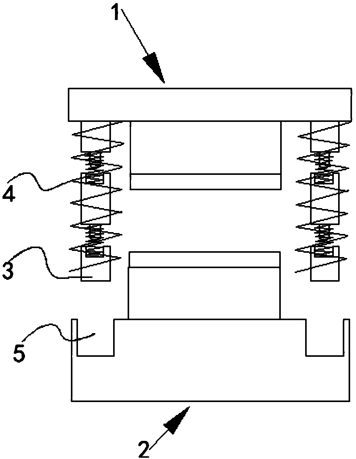
[0024] Embodiment: a buffer structure of precision stamping die, such as Figure 1-Figure 4 As shown, the stamping die comprises an upper die 1 and a lower die 2, the lower end of the upper die is provided with guide posts 3, and the guide posts are provided with four and are respectively located at four corners of the lower end of the upper die. , the outer circumference of the guide column is provided with a first spring 4, and the first spring is fixedly connected with the upper mold; the upper end of the lower mold is provided with four guide holes 5 that cooperate with the guide column;

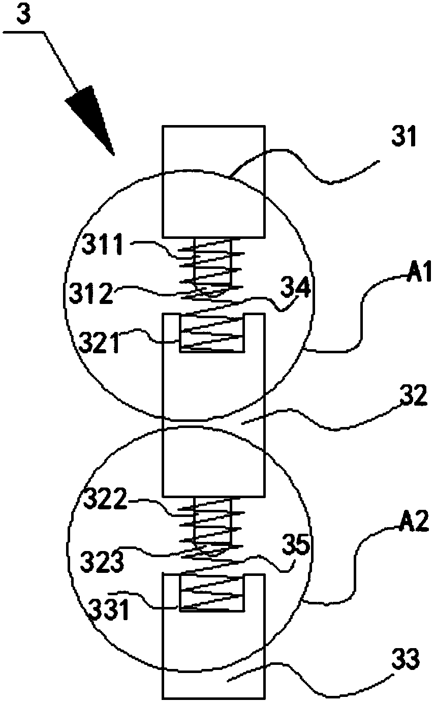
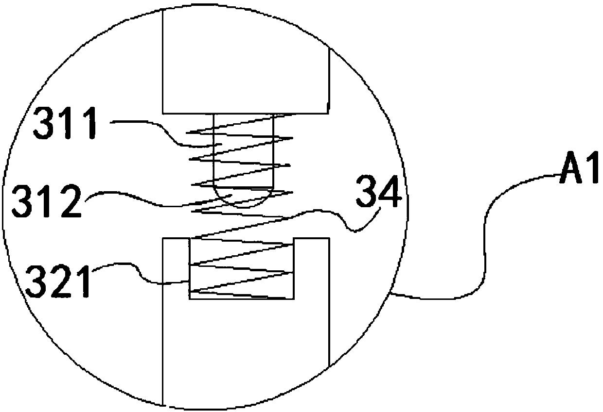
[0025] Each of the guide columns includes a first section guide column 31 at the top, a second section guide column 32 in the middle and a third section guide column 33 below, the first section guide column and the second section guide column The guide posts are connected by a second spring 34, the second section guide posts are connected with the third section guide posts by a third spr...


PUM


Abstract

The invention discloses a buffering structure of a precise punching die. The punching die comprises an upper die body and a lower die body. Guiding columns are arranged at the lower end of the upper die body, first springs are arranged on the peripheries of the guiding columns, and guiding holes are formed in the upper end of the lower die body. Each guiding column comprises a first-section guiding column body, a second-section guiding column body and a third-section guiding column body, wherein the first-section guiding column body and the second-section guiding column body are connected through a second spring, the second-section guiding column body and the third-section guiding column body are connected through a third spring, a first protruding block is arranged at the lower end of thefirst-section guiding column body, a first groove is formed in the upper end of the second-section guiding column body, a second protruding block is arranged at the lower end of the second-section guiding column body, and a second groove is formed in the upper end of the third-section guiding column body. The provided buffering structure of the precise punching die can effectively relieve vibration, the service life of the punching die is prolonged, the structure is simple, and design is reasonable.

Description

technical field [0001] The invention relates to the field of hardware processing machinery, in particular to a buffer structure of a precision stamping die. Background technique [0002] Stamping parts are generally realized by cold stamping of a stamping die. The stamping die generally includes an upper die and a lower die. The parts to be stamped are placed on the lower die, and the upper die moves downward under the action of the press. After the workpiece to be stamped is acted on, the workpiece to be stamped is deformed under force, and then becomes the required body stamping part. A working limit block is usually set on the upper surface of the lower die, and the upper die will contact with the working limit block when it goes down, so as to realize the movement limit of the upper die. However, the contact between the upper die and the working limit block is dead, and the two are in rigid contact. Due to the high pressure output by the press, the force between the upp...

Claims


Application Information

Patent Timeline
Patent Type & Authority Applications(China)
IPC IPC(8): B21D37/12F16F15/08
Inventor 付朝
Owner 苏州天朋精密元器件有限公司
Why Eureka
Try Eureka