Multi-rib and skin co-curing mold combining positioning frame and multiple female mold bodies

A technology for curing molds and positioning frames, applied in the field of molds, can solve the problems of low positioning accuracy of ribs, difficulty in demoulding, and difficulty in ensuring smooth co-curing bonding, etc., to achieve simple structure, simplified processing technology, and high bonding quality Guaranteed effect

Inactive Publication Date: 2018-01-19
CHENGDU AIRCRAFT INDUSTRY GROUP
View PDF1 Cites 6 Cited by
  • Summary
  • Abstract
  • Description
  • Claims
  • Application Information

AI Technical Summary

Problems solved by technology

However, under the current technical conditions, the existing bonding tooling has problems such as low positioning accuracy of the

Method used


Image

  • Multi-rib and skin co-curing mold combining positioning frame and multiple female mold bodies
  • Multi-rib and skin co-curing mold combining positioning frame and multiple female mold bodies
  • Multi-rib and skin co-curing mold combining positioning frame and multiple female mold bodies

Examples


Example Embodiment

[0020] Example 1:

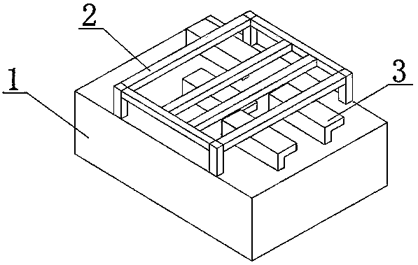
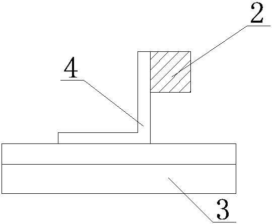
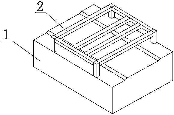
[0021] Such as figure 1 As shown, in this embodiment, a multi-reinforced skin co-curing mold composed of a positioning frame and a multi-female mold includes a support frame on which a working platform is formed on the upper surface for placing the skin. A plurality of feet are provided at the bottom and pass through the feet A positioning frame 2 detachably installed on the working platform and a plurality of female molds 3 arranged on the positioning frame 2 to position the ribs. When in use, the skin is placed on the working platform of the supporting frame 1, the positioning frame 2 is placed on the skin and the feet of the positioning frame 2 are connected with the working platform. Since the positioning frame 2 can be detachably installed on the work platform, the positioning frame 2 has a relatively fixed position relative to the work platform, and the positioning frame 2 is used as a positioning reference to position the skin. In this embodiment, the ...

Example Embodiment

[0022] Example 2:

[0023] On the basis of the above-mentioned embodiment, in this embodiment, the positioning frame 2 and the supporting frame 1 are threadedly connected. Use threaded connection to realize detachable function. In order to realize the threaded connection, a flange or a plate with a hole is arranged on the supporting leg, and a threaded hole is arranged on the supporting frame 1. When installing, the screw is inserted through the flange or the hole and the threaded hole is matched and installed. In this embodiment, there are at least two screw connections. When it is necessary to use the female mold 3 to compress the skin, the threaded connection between the positioning frame 2 and the support frame 1 is used to provide a pressing force for pressing the skin. In this embodiment, other undescribed parts are the same as the content of the foregoing embodiment, so they will not be repeated.

Example Embodiment

[0024] Example 3:

[0025] On the basis of the foregoing embodiment, in this embodiment, an A positioning pin is connected between the positioning frame 2 and the supporting frame 1. The positioning frame 2 and the support frame 1 are respectively provided with corresponding pin holes to facilitate the installation of the A positioning pins, and the A positioning pins can improve the positioning accuracy of the positioning frame 2 and the support frame 1. This is beneficial to improve the positioning accuracy of the skin and the accuracy of the relative position of the skin and the ribs, thereby helping to ensure the quality of the bonding. In this embodiment, other undescribed parts are the same as the content of the foregoing embodiment, so they will not be repeated.


PUM


Abstract

The invention discloses a multi-rib and skin co-curing mold combining a positioning frame and multiple female mold bodies. The multi-rib and skin co-curing mold combining the positioning frame and themultiple female mold bodies comprises a supporting frame, the positioning frame and the multiple female mold bodies, wherein a working platform for holding a skin is formed on the upper surface of the supporting frame; a plurality of supporting feet are arranged on the bottom of the positioning frame, and the positioning frame is detachably installed on the working platform through the supportingfeet; and the female mold bodies are arranged on the positioning frame so as to position ribs. The multi-rib and skin co-curing mold combining the positioning frame and the multiple female mold bodies has the beneficial effects that a special fixture is provided for glue joint of the skin and the ribs, accurate positioning of the skin and the ribs can be achieved, and thus the glue joint qualityof the skin and the ribs is improved. In addition, the multi-rib and skin co-curing mold combining the positioning frame and the multiple female mold bodies is simple in structure, convenient to use,beneficial for one-time forming so as to simplify processing technologies, and beneficial for improving glue joint efficiency.

Description

technical field [0001] The invention relates to the field of molds, in particular to a multi-rib skin co-curing mold combined with a positioning frame and multiple female molds. Background technique [0002] At present, the application area of ​​composite materials in civil and military aircraft continues to increase, the performance requirements continue to increase, and more and more applications are applied to the main load-bearing structures. Therefore, the structure of composite material components is becoming more and more complex, and the requirements for shape accuracy and the position, shape, and molding quality of each part inside the entire component are getting higher and higher. At the same time, these composite components also need to be glued or riveted with other parts to form a closed overall box together. Therefore, the position accuracy and surface quality of the parts in the formed composite member, that is, the ribs, are required to meet the requirement...

Claims


Application Information

Patent Timeline
IPC IPC(8): B29C35/02B29C33/00
Inventor 陈霞邵维平
Owner CHENGDU AIRCRAFT INDUSTRY GROUP
Why Eureka
Try Eureka