Photogravure press and squeegee device thereof

A technology of gravure printing machines and printing rollers, which is applied in the direction of gravure rotary printing machines, printing machines, rotary printing machines, etc., can solve problems such as missing printing, white spots in graphics and text, and affect product quality, so as to reduce the degree of damage, High ink scraping efficiency and good ink cleaning effect

Active Publication Date: 2018-01-19
东莞市信彩包装有限公司
View PDF9 Cites 7 Cited by
  • Summary
  • Abstract
  • Description
  • Claims
  • Application Information

AI Technical Summary

Problems solved by technology

The way that this scraping device uses air blowing to blow off excess ink on the surface of the printing plate cylinder has the following disadvantages: blowing air towards the printing plate cylinder can indeed blow off most of the ink on the surface of the printing plate cylinder, but due to the viscosity of the ink and the Under the action of its internal tension, a layer of ink film will remain on the surface of the printing plate cylinder, which will cause undesired lines on the printed matter and affect product quality; moreover, blowing air towards the printing plate roller brush will also remove the sunken pattern. The ink stored in the text part is blown away, resulting in white spots and missing printing in the graphic part of the product

Method used


Image

  • Photogravure press and squeegee device thereof
  • Photogravure press and squeegee device thereof
  • Photogravure press and squeegee device thereof

Examples


Embodiment 1

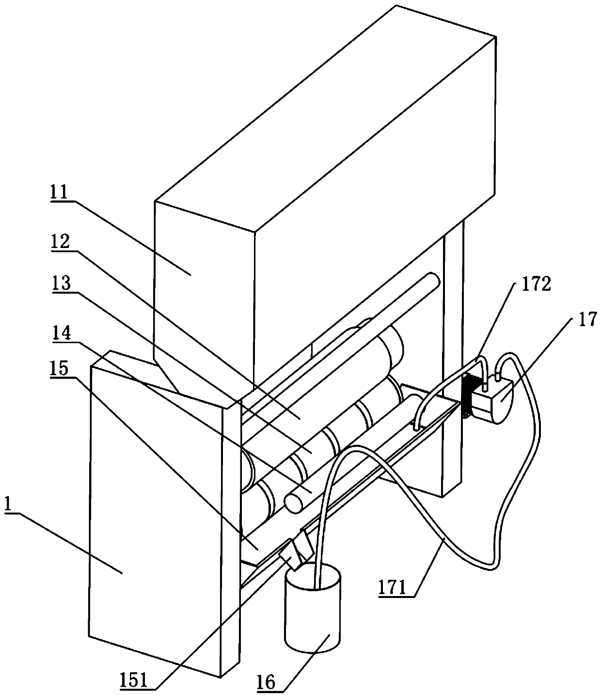
[0045] Embodiment one, a kind of scraping device of gravure printing machine, such as figure 1 As shown, it includes a frame 1, an oven 11 is arranged above the frame 1, an embossing roller 12 of rubber material is arranged between the frame 1, and a printing roller 13 is arranged under the embossing roller 12, and the printing roller 13 and the embossing roller There is a very small gap between the 12, the printing roller 13 is provided with a gravure plate for printing pictures and texts, an ink roller 14 is arranged against the printing roller 13, an ink pan 15 filled with ink is arranged under the ink roller 14, and The ink roller 14 is immersed in ink.

[0046] One side of the ink tray 15 is provided with an oil outlet 151, and an ink barrel 16 is arranged under the oil outlet 151. An oil suction pipe 171 is arranged in the ink barrel 16, and the end of the oil suction pipe 171 away from the ink barrel 16 is connected with a pneumatic diaphragm pump 17. The pneumatic dia...

Embodiment 2

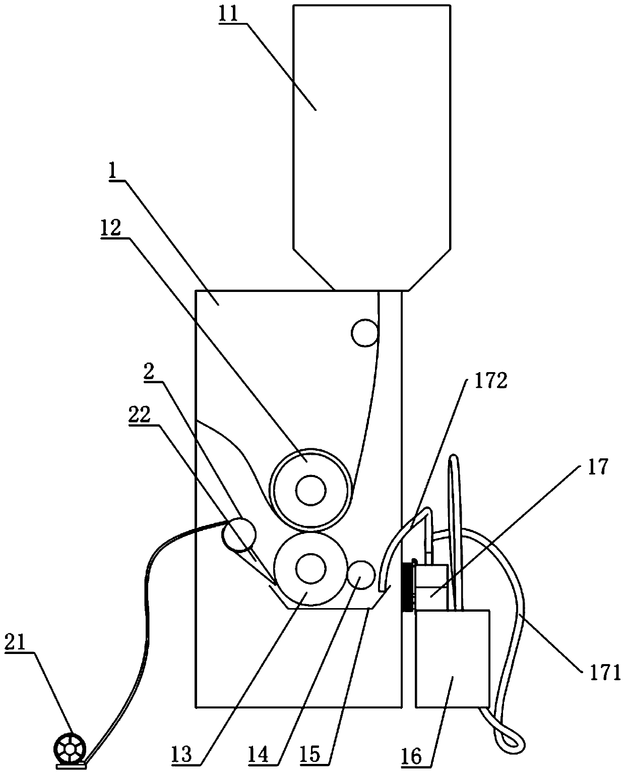
[0050] Embodiment 2, a gravure printing machine scraping device, differs from Embodiment 1 in that, as figure 2 As shown, in the printing process of Embodiment 1, before the ink in the graphic part is printed on the film, the ink on the surface of the entire printing roller 13 needs to be scraped off so that only the graphic part is stored on the entire printing roller 13. The ink is printed onto the film to get the desired pattern. For this reason, one side of the printing roller 13 is provided with the air jet tube 2 connected to the blower 21, the below of the air jet tube 2 is connected with the air flow channel 22 arranged towards the printing roll 13 tangential direction, the cross section of the air flow channel 22 is from the air jet tube 2 One end of the air flow channel 22 gradually becomes smaller to the other end, and the air injection direction of the air flow channel 22 is opposite to the linear velocity direction of the printing roller 13 near the air outlet of...

Embodiment 3

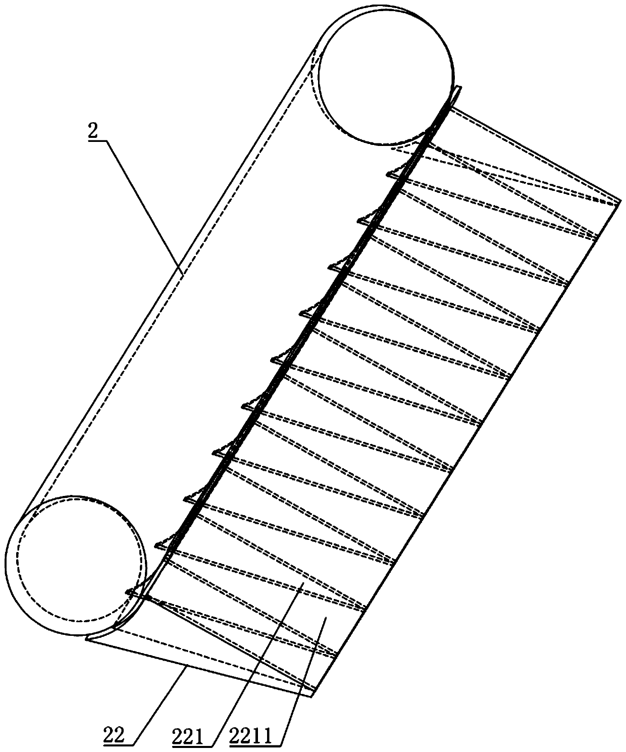
[0053] Embodiment three, a gravure printing machine scraping device, differs from embodiment two in that, as figure 2 , 3 , 4 and 5, several partitions 221 are evenly distributed along the axial direction of the printing roller 13 in the air flow channel 22, and are used to divide the air flow channel 22 into several air chambers 2211. A slot 222 is provided on the side of each air chamber 2211 away from the printing roller 13 , and an arc-shaped insert 23 is arranged in the slot 222 . The arc-shaped insert 23 has the same radius of curvature as the air jet 2 .

[0054] Such as Figure 5 As shown, a pair of hook edges 231 are provided on both sides of the arc-shaped flashboard 23 on the cylinder wall of the jet tube 2 toward the arc-shaped flashboard 23, and a gap for the arc-shaped flashboard 23 to slide is formed between the hook edges 231 and the jet barrel 2. Guide groove 2311.

[0055] Specific instructions:

[0056] The high-pressure air ejected from the air flow ch...


PUM


Abstract

The invention discloses a photogravure press and a squeegee device thereof, belongs to the field of photogravure presses, and aims to provide a photogravure press squeegee device which can overcome the defect that ink stored in sunken image-text areas is blown away when ink on the surfaces of printing rollers is removed through an air blowing method. According to the technical scheme, the photogravure press squeegee device is characterized in that the squeegee device comprises an imprinting roller and a printing roller; an ink plate is arranged under the printing roller; an air blowing barrelconnected with an air blower is arranged on one side of the printing roller; an air flowing channel is formed in the side wall, facing the printing roller, of the air blowing barrel; the air flowing channel is formed in the tangential direction of the printing roller; the air outlet direction of the air flowing channel is opposite to the line speed direction of the position, close to the air flowing channel, of the printing roller; a plurality of partition plates are evenly distributed in the air flowing channel in the axial direction of the printing roller; the air flowing channel is dividedinto a plurality of air chambers through the partition plates; insertion grooves are formed in the positions which are located on the sides, away from the printing roller, of all the air chambers, ofthe joint of the air flowing channel and the air blowing barrel; and arc-shaped insertion plates are arranged in the insertion grooves.

Description

technical field [0001] The invention relates to the field of gravure printing machines, in particular to a gravure printing machine and a scraping device thereof. Background technique [0002] A gravure printing machine is a machine that uses gravure plates for printing. The graphic part of the printing plate is sunken, and the blank part is on the same plane as the outer circle of the printing plate cylinder. By applying ink to the concave part of the printing plate, using a doctor blade or other methods to remove excess ink, and then under the action of printing pressure, the ink is transferred to the substrate to complete the printing process. Gravure printing has clear layers, thick and bright ink layer, uniform ink color, can truly reproduce the effect of the original manuscript, and the printing speed is fast. It is one of the most widely used printing methods at present. [0003] The inking devices of the gravure printing machine mainly include immersion type, ink t...

Claims


Application Information

Patent Timeline
Patent Type & Authority Applications(China)
IPC IPC(8): B41F9/08B41F9/10
Inventor 邱诗妍
Owner 东莞市信彩包装有限公司
Why Eureka
Try Eureka