Locking device of bicycle saddle and bicycle thereof

A bicycle seat and locking device technology, applied in bicycle saddles, bicycle accessories, transportation and packaging, etc., can solve the problems of reducing the service life of steel balls, insufficient bearing capacity of a single positioning steel ball, and accelerating the wear of steel balls.

Inactive Publication Date: 2018-01-19
NINGBO UNIV
View PDF6 Cites 5 Cited by
  • Summary
  • Abstract
  • Description
  • Claims
  • Application Information

AI Technical Summary

Problems solved by technology

[0003] The bicycle lifting device with the above structure has the following problems: only a single positioning steel ball is used to fix the relative position of the lifting rod and the fixing sleeve, and the bearing force of a single positioning steel ball may not be enough. At a certain point or on one side, when the weight of the human body is applied, the positioning steel ball on one side will easily make the position of the lifting rod and the fixing sleeve deviate
Cause uneven force, accelerate the wear of steel balls, and reduce the service life of steel balls
At the same time, the positioning sleeve is located on one side of the fixed sleeve, and it is not convenient to manually adjust the lifting of the seat

Method used


Image

  • Locking device of bicycle saddle and bicycle thereof
  • Locking device of bicycle saddle and bicycle thereof
  • Locking device of bicycle saddle and bicycle thereof

Examples


Embodiment 1

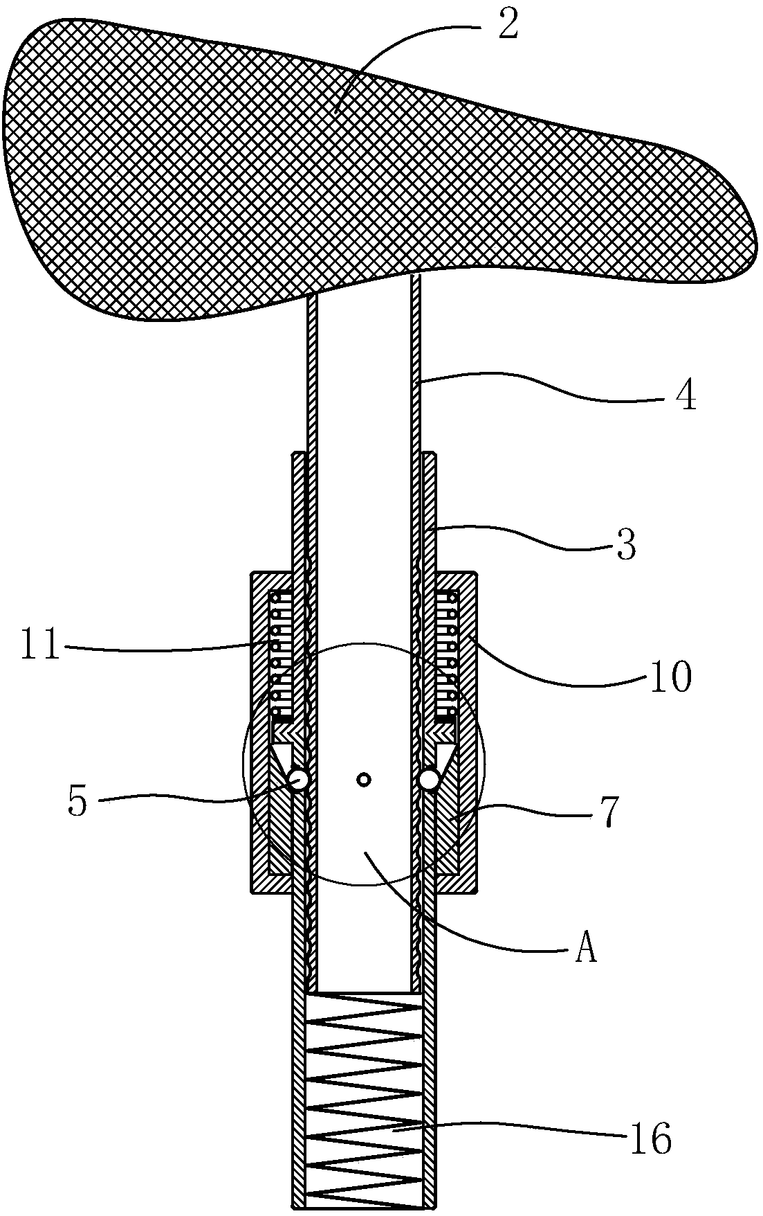
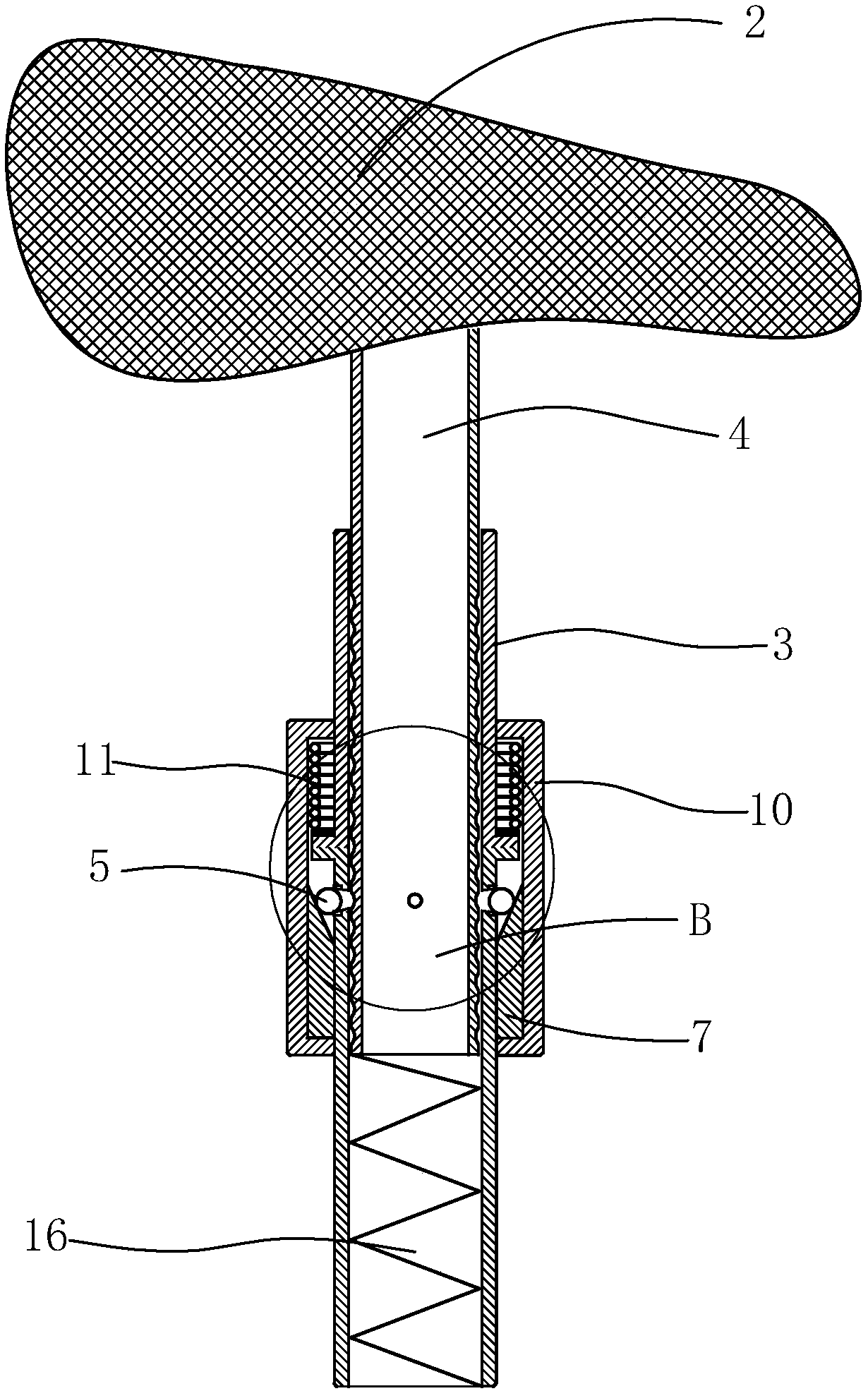
[0027] The locking device 1 includes a plurality of limit steel balls 5 annularly distributed on the standpipe 3 that can move laterally and remain in the standpipe all the time, an annular groove 6 arranged longitudinally on the outer wall of the core pipe 4 and sleeved The inner taper sleeve 7 with inclined push surface 71 that can move up and down outside the standpipe 3, the inner taper sleeve 7 is used to push the limit steel ball 5 into the annular groove 6, thereby locking the relative position of the core tube 4 and the standpipe 3, Thereby the height of vehicle seat 2 is fixed. Specifically, the first state, such as figure 1 , Figure 4 As shown, the inclined push surface 71 on the inner tapered sleeve 7 pushes the limit steel ball 5 inwardly into one of the annular grooves 6 of the core tube 4, and the height of the seat 2 is fixed; the second state, such as figure 2 , Figure 5 As shown, the inclined push surface 71 of the inner tapered sleeve 7 leaves the limit...

Embodiment 2

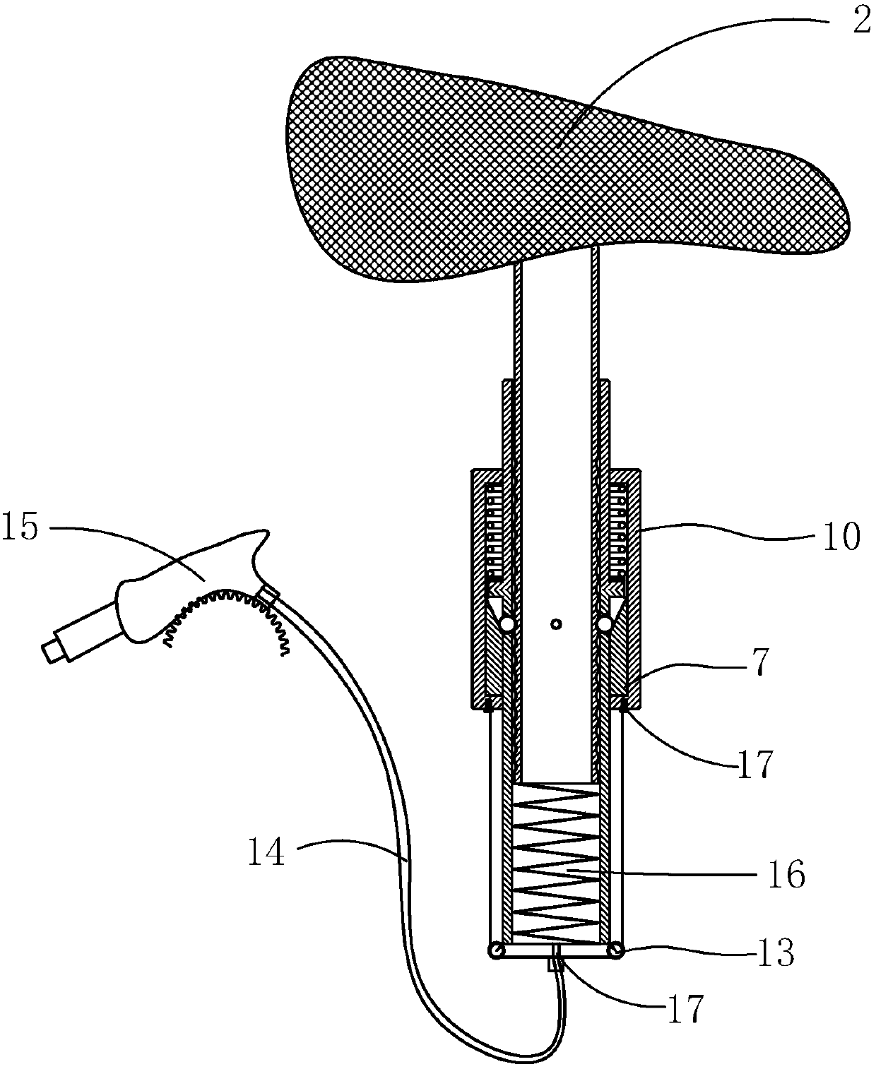
[0033] All the other parts are the same as Embodiment 1, the difference is: as image 3 As shown, the two ends of the bottom of the standpipe 3 are symmetrically provided with pulleys 13, and the two ends of the bottom of the stretch coat 10 are symmetrically fixed with stay ropes 14, and the two strands of stay ropes 14 are connected together after bypassing the pulleys 13. Preferably, It can be connected to a stay rope fixed mount 17, which is connected to the outer wall of the standpipe 3 bottom, and then the stay rope 14 is connected to the joystick 15, which is installed on the vehicle frame Or seat 2. In this embodiment, the user only needs to use the joystick 15 to pull the pull cord 14 so that the stretch coat 10 moves up or down, and finally controls the inclined push surface 71 to push the limit steel ball 5 or leave the limit steel ball 5, Adjust the relative positional relationship between the core tube 4 and the vertical tube 3 . The stay cord 14 is fixed on the...

Embodiment 3

[0036] The remaining parts are the same as in Embodiment 1, except that: preferably, the standpipe 3 is provided with annularly distributed through grooves 8, and a plurality of steel ball cages (not shown) are installed in the annularly distributed through grooves 8, limiting The position steel ball 5 is installed in the steel ball cage, and the limit steel ball 5 can move laterally in the steel ball cage in a limited range. When the inclined push surface 71 leaves the limit steel ball 5, the limit steel ball 5 leaves the core tube 4 under the action of its own weight The annular groove 6 will not completely break away from the through groove 8; specifically: as Figure 4 As shown, when the inclined push surface 71 pushes the limit steel ball 5 inward, the limit steel ball 5 moves inward in the steel ball holder and a part of the limit steel ball 5 enters the annular groove 6, thereby locking the core tube 4 and the vertical The relative position of pipe 3, fixes the height o...


PUM


Abstract

The invention discloses a bicycle which comprises a frame and a saddle. A vertical pipe is arranged on the frame, a core pipe is arranged below the saddle, a locking device is arranged between the core pipe and the vertical pipe and comprises multiple limiting steel balls annularly distributed on the vertical pipe and capable of transversely moving in a limited-amplitude manner, the limiting steelballs can be constantly held in the vertical pipe, and annular grooves in longitudinal arrangement and an inner taper sleeve sleeving outside the vertical pipe, capable of moving up and down and provided with an oblique pushing face are arranged on the outer wall of the core pipe. When the oblique pushing face on the inner taper sleeve inwards pushes and presses the limiting steel balls to enterone annular groove of the core pipe, height of the saddle is fixed; when the oblique pushing face of the inner taper sleeve leaves the limiting steel balls, the limiting steel balls move out of the annular groove of the core pipe, and the core pipe of the saddle and the vertical pipe on the frame can move up and down relatively. Relative position of the core pipe and the vertical pipe are limitedby utilizing the limiting steel balls in annular distribution, so that the locking device is higher in bearing capacity, and the saddle is less prone to deviation and more stable.

Description

technical field [0001] The invention relates to a mechanical locking device, in particular to a locking device of a bicycle saddle and a bicycle thereof. Background technique [0002] In order to facilitate the use of different groups of people, the height of the bicycle seat can be adjusted by itself and locked at a suitable position. The bicycle seat and the vehicle frame are usually fixed by bolts, and when the height of the bicycle seat needs to be adjusted, the bolts need to be loosened by tools such as a wrench. With this locking structure, it takes time and effort to adjust the height of the seat, and repeated adjustments are likely to reduce the service life of the bolts. The authorized announcement number is "CN203172816U", and the utility model patent named "bicycle lifting device" discloses a bicycle seat lifting device, including a lifting rod and a fixing sleeve. The bottom of the lifting rod is provided with a telescopic spring and inserted into the fixing sle...

Claims


Application Information

Patent Timeline
Patent Type & Authority Applications(China)
IPC IPC(8): B62J1/08
Inventor 孙腾缪馥星马少林李善恩
Owner NINGBO UNIV
Why Eureka
Try Eureka