Floor drain structure

A technology of floor drain and floor drain cover

Inactive Publication Date: 2018-01-19
DONGGUAN ZHIPEI ELECTROMECHANICAL TECH CO LTD
View PDF0 Cites 0 Cited by
  • Summary
  • Abstract
  • Description
  • Claims
  • Application Information

AI Technical Summary

Problems solved by technology

[0002] As people's requirements for the quality of life are getting higher and higher, the demand for home decoration materials is also increasing day by day. Daily necessities are not only satisfied with their simple functions, such as floor drains installed on the surface of kitchens, bathrooms or balconies. , although the floor drain can play a drainage role, but because the pipe is connected to the sewer, the peculiar smell in the sewer can easily reach the room from the pipe through the floor drain.
There are various changes in the shape of the existing floor drains, but the general structure is exhausted. Among them, the drains of the floor drains are all fixed. During installation, the drains need to be connected with the drains on the ground, and the connection must be very precise. , otherwise it is prone to water leakage, which not only limits the applicability of conventional floor drains, but also brings great inconvenience to users.

Method used


Image

  • Floor drain structure

Examples


Embodiment Construction

[0018] The present invention will now be described in further detail with reference to the accompanying drawings. These drawings are all simplified schematic diagrams, and only illustrate the basic structure of the present invention in a schematic manner, so they only show the structures related to the present invention.

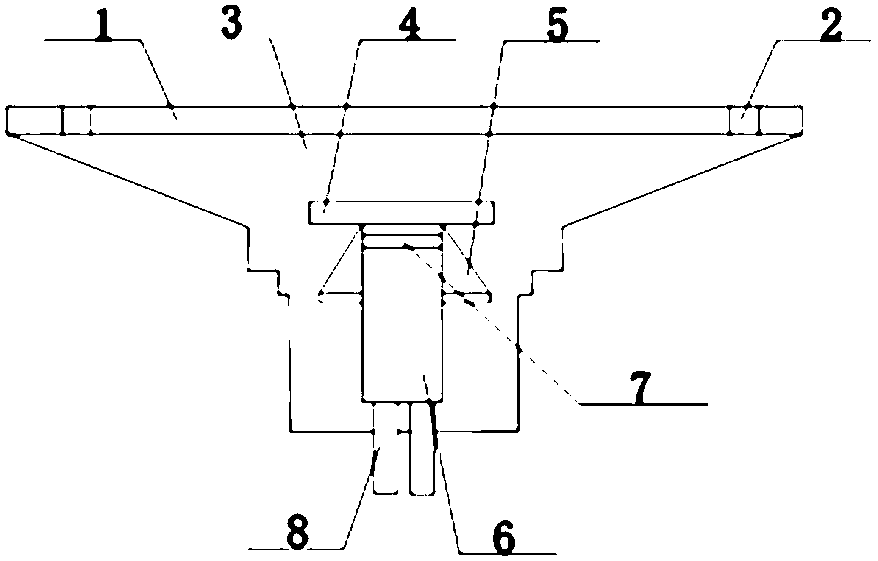
[0019] like figure 1 The preferred embodiment of the floor drain structure of the present invention shown includes a floor drain cover 1, the floor drain cover 1 is provided with a sealing structure 2 near both ends, the floor drain cover 1 is provided with a floor drain body 3 on the lower surface, and the floor drain cover 1 and the floor drain body 3 are arranged between the floor drain cover 1 and the floor drain body 3. There is an active connection between them, and a sealing gasket is installed at the joint. The sealing gasket is fixed on the lower surface of the floor drain cover 1 corresponding to the edge of the floor drain body 3, and the lower su...


PUM


Abstract

The invention discloses a floor drain structure. The floor drain structure comprises a floor drain cover. The floor drain cover is provided with sealing structures close to two end portions. A lower surface of the floor drain cover is provided with a floor drain body. The floor drain cover and the floor drain body are movably connected, and a sealing gasket is installed at the connection position.The sealing gasket is fixed on the lower surface, corresponding to an edge of the floor drain body, of the floor drain cover, and the lower surface of the floor drain cover is provided with a groovematched with the sealing gasket. A connecting pipe is disposed in the floor drain body and transversely arranged. A lower surface of the connecting pipe is provided with a drainage pipe communicated with the connecting pipe. The drainage pipe is equipped with a filtering device at a position close to the connecting pipe. Two side surfaces of the drainage pipe are provided with guard boards of a triangular structure. The bottom of the drainage pipe is provided with counterweight blocks, the top of each counterweight block is fixedly connected with the drainage pipe, and the bottom of each counterweight block extends out of an outer side surface of the bottom of the floor drain body. The floor drain structure can be smoothly installed and used in various environments, floor drain adaptability is improved, the floor drain structure has good sealing connection performance, the emptying effect can be effectively increased, impurities such as silt can be prevented from entering the floor drain structure and further arriving the indoor space, the draining effect is perfect, and sewage can be drained timely.

Description

technical field [0001] The invention relates to a drainage purification facility, in particular to a floor drain structure. Background technique [0002] As people's requirements for the quality of life are getting higher and higher, the demand for home decoration materials is also increasing day by day, and the daily necessities are not only satisfied with their simple functions, such as floor drains installed on the kitchen, bathroom or balcony floor. , Although the floor drain can play a role in drainage, but because the pipeline is connected with the sewer, the odor in the sewer is easy to reach the room through the floor drain from the pipeline. The existing floor drains have various changes in shape, but the general structure is exhausted. The drains of the floor drains are all fixed. During installation, the drains need to be docked with the drains on the ground, and the docking must be very precise. Otherwise, the problem of water leakage is likely to occur, which n...

Claims


Application Information

Patent Timeline
Patent Type & Authority Applications(China)
IPC IPC(8): E03F5/04
Inventor 黄旭
Owner DONGGUAN ZHIPEI ELECTROMECHANICAL TECH CO LTD
Why Eureka
Try Eureka