Centralized distribution multiway switching valve

A technology of multi-way switching and centralized distribution, applied in multi-way valves, valve devices, cocks including cut-off devices, etc. High reliability and easy maintenance

Pending Publication Date: 2018-01-19
KUNMING UNIV OF SCI & TECH
View PDF0 Cites 2 Cited by
  • Summary
  • Abstract
  • Description
  • Claims
  • Application Information

AI Technical Summary

Problems solved by technology

At present, in the centralized distribution and switching of liquid flow, manual gate valves or electromagnetic gate valves are mostly used to assemble and integrate to meet the requirements. In this way, the more target points, the more pipe networks, the more gate valves are required, and the more difficult the assembly and integration are. The larger the space, the higher the input cost, and the higher failure rate, the maintenance is extremely inconvenient, which limits the development of multi-objective applications

Method used


Image

  • Centralized distribution multiway switching valve
  • Centralized distribution multiway switching valve
  • Centralized distribution multiway switching valve

Examples


Embodiment 1

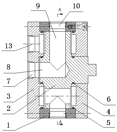
[0023] Embodiment 1: as figure 1 As shown, a centralized distribution multi-way switching rotary valve includes a valve sleeve 1, a valve core 2, a left end cover 3, a right end cover 4, a sealing ring I5 and a sealing ring II6; the valve core 2 is installed in the valve sleeve 1 through clearance fit , the left end cover 3 is fixed on the left end surface of the valve sleeve 1, the right end cover 4 is fixed on the right end surface of the valve sleeve 1, the valve core 2 is respectively connected with the left end cover 3 and the right end cover 4 through bearings, and the sealing ring I5 is installed on the left end cover 3 and the On the right end cover 4, it is used to prevent the leakage between the left end cover 3 and the right end cover 4 and the valve sleeve 1; the sealing ring II6 is installed on the left and right shoulders of the spool 2, and is used to prevent the spool 2 from contacting the left end. Leakage between cap 3 and right end cap 4.

Embodiment 2

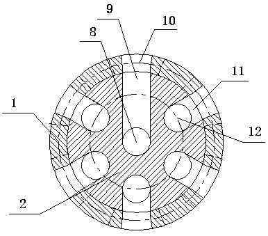
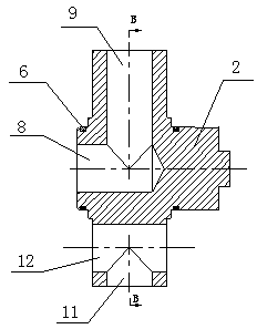
[0024] Embodiment 2: as Figure 1-4 As shown, a centralized distribution multi-way switching rotary valve includes a valve sleeve 1, a valve core 2, a left end cover 3, a right end cover 4, a sealing ring I5 and a sealing ring II6; the valve core 2 is installed in the valve sleeve 1 through clearance fit , the left end cover 3 is fixed on the left end surface of the valve sleeve 1, the right end cover 4 is fixed on the right end surface of the valve sleeve 1, the valve core 2 is respectively connected with the left end cover 3 and the right end cover 4 through bearings, and the sealing ring I5 is installed on the left end cover 3 and the On the right end cover 4, it is used to prevent leakage between the left end cover 3 and the right end cover 4 and the valve sleeve 1; the sealing ring II6 is installed on the left and right shoulders of the spool 2, and is used to prevent the spool 2 from contacting the left end. Leakage between cover 3 and right end cover 4;

[0025] The va...


PUM


Abstract

The invention relates to a centralized distribution multiway switching valve, and belongs to the field of agricultural and forestry greening machinery. The centralized distribution multiway switchingvalve comprises a valve sleeve, a valve core, a left end cover, a right end cover, a sealing ring I and a sealing ring II; and the valve core is mounted in the valve sleeve in a clearance fit mode, the left end cover is fixed on the left end face of the valve sleeve, the right end cover is fixed on the right end face of the valve sleeve, and the valve core is connected with the left end cover andthe right end cover through bearings; the sealing ring I is mounted on the left end cover and the right end cover and is used for preventing leakage between the left end cover and the right end coveras well as the valve sleeve; and the sealing ring II is mounted on a left shaft shoulder and a right shaft shoulder of the valve core. According to centralized distribution multiway switching valve, the number of paths can be selected according to requirements, and the paths are allocated to any target supplying place; and required driving elements are less, the valve integration is high, the structure is compact, reliability is high, and maintenance is convenient.

Description

technical field [0001] The invention relates to a centralized distribution multi-way switching rotary valve, which belongs to the field of agricultural and forest greening machinery. Background technique [0002] In the pumping process of irrigation, sprinkler irrigation, liquid fertilization, and pesticide spraying in agriculture, forestry, urban greening, medicinal material planting, greenhouse planting, etc., it is necessary to switch and distribute the liquid flow according to different target points. At present, in the centralized distribution and switching of liquid flow, manual gate valves or electromagnetic gate valves are mostly used to assemble and integrate to meet the requirements. In this way, the more target points, the more pipe networks, the more gate valves are required, and the more difficult the assembly and integration are. The larger the space, the higher the input cost, and the higher the failure rate, the maintenance is extremely inconvenient, which li...

Claims


Application Information

Patent Timeline
Patent Type & Authority Applications(China)
IPC IPC(8): F16K11/085F16K5/08F04B53/10
Inventor 吴张永刘远清何铭陈旭朱启晨杨春啟
Owner KUNMING UNIV OF SCI & TECH
Why Eureka
Try Eureka