Terminal device, circuit board assembly, flash unit and manufacturing method thereof
A technology of circuit board components and terminal equipment, applied in printed circuit components, optics, instruments, etc., can solve problems such as unfavorable, inflexible settings, poor heat dissipation, etc., to prolong service life, improve structural design flexibility, The effect of improving heat dissipation efficiency
- Summary
- Abstract
- Description
- Claims
- Application Information
AI Technical Summary
Problems solved by technology
Method used
Image
Examples
Embodiment 1
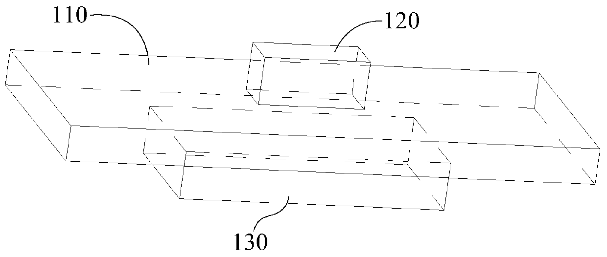
[0044] Please also refer to figure 1 and figure 2 , figure 1 It is a schematic diagram of the overall structure of an embodiment of the flash unit used in the terminal equipment of the present application, figure 2 yes figure 1 Example of a side view of the flash unit. It should be noted that the terminal devices referred to in the present invention include mobile phones, tablet computers, notebook computers, and wearable devices. In this embodiment, the flash assembly includes an FPC board 110 , a flash device 120 and a heat dissipation plate 130 . FPC: flexible circuit board, the abbreviation of Flexible Printed Circuit is FPC; it is generally a kind of highly reliable and excellent flexible printed circuit board made of polyimide or polyester film as the base material, with wiring It has the characteristics of high density, light weight, thin thickness and good bendability.
[0045] Specifically, the flashlight device 120 is mounted on one side surface of the FPC bo...
Embodiment 2
[0051] see image 3 , image 3 It is a schematic side view of the structure of another embodiment of the flashlight assembly used in terminal equipment in this application. The difference from the previous embodiment is that the heat dissipation plate 130 of the flashlight assembly in this embodiment is coated with a heat dissipation material 140 for Improve cooling efficiency. Wherein, the heat dissipation material 140 may be heat dissipation silicon grease.
[0052] see Figure 4 , Figure 4 yes image 3 A schematic front view of the structure of the flash unit in this embodiment; in this embodiment, the heat dissipation material 140 is arranged to completely cover the heat dissipation plate 130 . This arrangement structure can further improve the heat dissipation efficiency on the one hand, and on the other hand, the heat dissipation material 140 can completely cover the heat dissipation plate 130 to prevent the heat dissipation plate 130 from rusting (generally, the h...
Embodiment 3
[0055] Please also refer to Figure 5 and Figure 6 , Figure 5 It is a schematic side view of another embodiment of the flash unit used in the terminal device of the present application, Figure 6 yes Figure 5 The front view schematic diagram of the structure of the flash unit in the embodiment. The difference between this embodiment and the previous embodiment is that the heat dissipation material 140 covers a part of the heat dissipation plate 130, that is, the heat dissipation material 140 covers it from one side of the heat dissipation plate 130 Set up the structure.
PUM
 Abstract
Description
Claims
Application Information
 - R&D
- Intellectual Property
- Life Sciences
- Materials
- Tech Scout
- Unparalleled Data Quality
- Higher Quality Content
- 60% Fewer Hallucinations
Browse by: Latest US Patents, China's latest patents, Technical Efficacy Thesaurus, Application Domain, Technology Topic, Popular Technical Reports.
© 2025 PatSnap. All rights reserved.Legal|Privacy policy|Modern Slavery Act Transparency Statement|Sitemap|About US| Contact US: help@patsnap.com


