

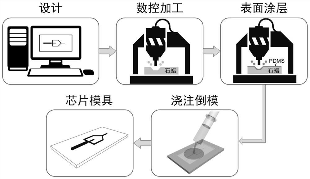
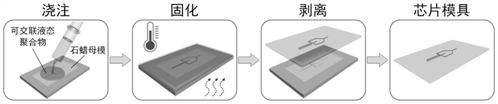
A method for making microfluidic chip molds by using numerical control engraving technology combined with paraffin substrates
A technology of microfluidic chip and numerical control engraving machine, applied in the field of micromachining, can solve the problems of restricting the development and practical application of microfluidic technology, harsh processing environment, complex processing process, etc., to accelerate research and practical application, and easy to operate. , The effect of low processing cost
- Summary
- Abstract
- Description
- Claims
- Application Information
AI Technical Summary
Problems solved by technology
Method used
Image

Examples
Embodiment 1
[0053] To make a focused droplet microfluidic chip mold based on epoxy glue, the specific steps are:
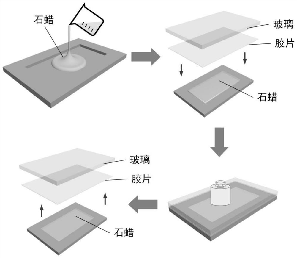
[0054](1) Production of paraffin substrate: A hollowed glass plate and another flat glass plate are bonded with double-sided tape to form a flat plate with a cavity; the plate is placed on a 100°C hot plate, and the cavity Inject melted microcrystalline wax into the cavity so that the paraffin liquid level is slightly higher than the upper surface of the cavity; then press a piece of film and a flat glass plate on the paraffin liquid; turn off the power supply of the hot plate to cool and solidify the paraffin liquid; wait for the paraffin to cool After reaching room temperature, remove the glass cover and peel off the film to obtain a paraffin substrate with a smooth surface. The preparation process is as follows: figure 2 shown.
[0055] (2) Paraffin wax master mold engraving: First, use AutoCAD software to draw the pipeline graphics of the focused droplet microfluidic ch...
Embodiment 2
[0059] To make a focused droplet microfluidic chip mold based on ultraviolet glue, the specific steps are:
[0060] (1) Production of paraffin substrate: A hollowed glass plate and another flat glass plate are bonded with double-sided tape to form a flat plate with a cavity; the plate is placed on a 100°C hot plate, and the cavity Inject melted microcrystalline wax into the cavity so that the paraffin liquid level is slightly higher than the upper surface of the cavity; then press a piece of film and a flat glass plate on the paraffin liquid; turn off the power supply of the hot plate to cool and solidify the paraffin liquid; wait for the paraffin to cool After reaching room temperature, remove the glass cover and peel off the film to obtain a paraffin substrate with a smooth surface. The preparation process is as follows: figure 2 shown.
[0061] (2) Paraffin wax master mold engraving: First, use AutoCAD software to draw the pipeline graphics of the focused droplet microflu...
Embodiment 3
[0065] To make a focused droplet microfluidic chip mold based on alumina ceramics, the specific steps are:
[0066] (1) Production of paraffin substrate: A hollowed glass plate and another flat glass plate are bonded with double-sided tape to form a flat plate with a cavity; the plate is placed on a 100°C hot plate, and the cavity Inject melted microcrystalline wax into the cavity so that the paraffin liquid level is slightly higher than the upper surface of the cavity; then press a piece of film and a flat glass plate on the paraffin liquid; turn off the power supply of the hot plate to cool and solidify the paraffin liquid; wait for the paraffin to cool After reaching room temperature, the glass cover plate was removed, and the film was peeled off to obtain a paraffin substrate with a smooth surface.
[0067] (2) Paraffin wax master mold engraving: First, use AutoCAD software to draw the pipeline graphics of the focused droplet microfluidic chip. The width and depth of the w...
PUM
 Abstract
Description
Claims
Application Information