
Terminal equipment, circuit board assembly, flashlight assembly and manufacturing method of flashlight assembly

A technology for circuit board assembly and terminal equipment, which is applied in printed circuit components, optics, instruments, etc., can solve the problems of poor heat dissipation performance, disadvantage, and inability to set flexibly, so as to improve heat dissipation efficiency, prolong service life, and improve structure. The effect of design flexibility

Active Publication Date: 2018-01-19
GUANGDONG OPPO MOBILE TELECOMM CORP LTD
View PDF4 Cites 0 Cited by
  • Summary
  • Abstract
  • Description
  • Claims
  • Application Information

AI Technical Summary

Problems solved by technology

[0002] The flashlight is an essential functional structure of mobile phones and other terminal equipment. In the prior art, the flashlight device is generally fixed on the main PCB board. Since the main PCB board is a hard board, this leads to the Z direction between the flashlight device and the back cover of the mobile phone. (The vertical direction of the display screen) spacing is relatively fixed, and the design engineer cannot flexibly set its position when designing the flash device, and it is not conducive to the design of reducing the overall thickness of the terminal equipment; in addition, because the flash device is fixed on the main body PCB board, resulting in poor heat dissipation performance, which in turn affects the service life of the flash device

Method used


Image

  • Terminal equipment, circuit board assembly, flashlight assembly and manufacturing method of flashlight assembly
  • Terminal equipment, circuit board assembly, flashlight assembly and manufacturing method of flashlight assembly
  • Terminal equipment, circuit board assembly, flashlight assembly and manufacturing method of flashlight assembly

Examples


Embodiment 1

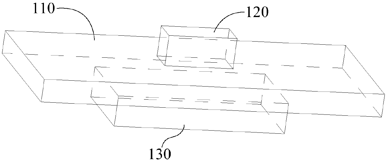
[0044] Please also refer to figure 1 with figure 2 , figure 1 It is a schematic diagram of the overall structure of an embodiment of the flash unit used in the terminal equipment of the present application, figure 2 yes figure 1 Example of a side view of the flash unit. It should be noted that the terminal devices referred to in the present invention include mobile phones, tablet computers, notebook computers, and wearable devices. In this embodiment, the flash assembly includes an FPC board 110 , a flash device 120 and a heat dissipation plate 130 . FPC: flexible circuit board, the abbreviation of Flexible Printed Circuit is FPC; it is generally a kind of highly reliable and excellent flexible printed circuit board made of polyimide or polyester film as the base material, with wiring It has the characteristics of high density, light weight, thin thickness and good bendability.

[0045] Specifically, the flashlight device 120 is mounted on one side surface of the FPC b...

Embodiment 2

[0051] see image 3 , image 3 It is a schematic side view of the structure of another embodiment of the flashlight assembly used in terminal equipment in this application. The difference from the previous embodiment is that the heat dissipation plate 130 of the flashlight assembly in this embodiment is coated with a heat dissipation material 140 for Improve cooling efficiency. Wherein, the heat dissipation material 140 may be heat dissipation silicon grease.

[0052] see Figure 4 , Figure 4 yes image 3 A schematic front view of the structure of the flash unit in this embodiment; in this embodiment, the heat dissipation material 140 is arranged to completely cover the heat dissipation plate 130 . This arrangement structure can further improve the heat dissipation efficiency on the one hand, and on the other hand, the heat dissipation material 140 can completely cover the heat dissipation plate 130 to prevent the heat dissipation plate 130 from rusting (generally, the h...

Embodiment 3

[0055] Please also refer to Figure 5 with Image 6 , Figure 5 It is a schematic side view of another embodiment of the flash unit used in the terminal device of the present application, Image 6 yes Figure 5 The front view schematic diagram of the structure of the flash unit in the embodiment. The difference between this embodiment and the previous embodiment is that the heat dissipation material 140 covers a part of the heat dissipation plate 130, that is, the heat dissipation material 140 covers it from one side of the heat dissipation plate 130 Set up the structure.


PUM


Abstract

The invention provides terminal equipment, a circuit board assembly, a flashlight assembly and a manufacturing method of the flashlight assembly. The flashlight assembly comprises an FPC board, a flashlight device and a cooling panel, wherein the flashlight device is stuck on one side surface of the FPC board and electrically connected with the FPC board; the cooling panel is stuck on the other side surface of the FPC board and the cooling panel and the flashlight device are oppositely arranged at two different sides of the FPC board; and the cooling panel is used for cooling the flashlight device. According to the flashlight assembly provided by the embodiment of the invention, on one hand, the flashlight device is combined with the FPC board, so that the structural design flexibility ofthe flashlight device in the terminal equipment is improved; and on the other hand, a reinforcing plate of the PFC board is utilized as the cooling panel, so that of the cooling efficiency of the flashlight device can be greatly improved and the service life of the flashlight device is prolonged.

Description

technical field [0001] The present invention relates to the technical field of the flexible circuit board assembly structure of terminal equipment, in particular to a terminal equipment, a circuit board assembly, a flash lamp assembly and a manufacturing method thereof. Background technique [0002] The flashlight is an essential functional structure of mobile phones and other terminal equipment. In the prior art, the flashlight device is generally fixed on the main PCB board. Since the main PCB board is a hard board, this leads to the Z direction between the flashlight device and the back cover of the mobile phone. (The vertical direction of the display screen) spacing is relatively fixed, and the design engineer cannot flexibly set its position when designing the flash device, and it is not conducive to the design of reducing the overall thickness of the terminal equipment; in addition, because the flash device is fixed on the main body The PCB board leads to its poor heat...

Claims


Application Information

Patent Timeline
IPC IPC(8): G03B15/05H05K1/02G03B30/00
Inventor 陈鑫锋
Owner GUANGDONG OPPO MOBILE TELECOMM CORP LTD
Learn More