Real-time positioning method and device

A real-time positioning and time technology, applied in image data processing, instruments, computing and other directions, can solve the problems of small tracking area, low data refresh rate, unable to guarantee data refresh rate, etc., to achieve the effect of improving refresh rate and reducing time

Active Publication Date: 2018-01-19
BEIJING SWEET TECH CO LTD
View PDF6 Cites 4 Cited by
  • Summary
  • Abstract
  • Description
  • Claims
  • Application Information

AI Technical Summary

Problems solved by technology

[0004] However, since only one transmitter works in the same period of time when multiple transmitters are cascaded, when the number of transmitters is large, the data refresh rate is low; in order to increase the data refresh rate, the number of transmitters can be reduced, The reduction in the number of transmitters leads to a smaller tracking area, so it is impossible to guarantee the data refresh rate while expanding the tracking area

Method used


Image

  • Real-time positioning method and device
  • Real-time positioning method and device
  • Real-time positioning method and device

Examples


Embodiment 1

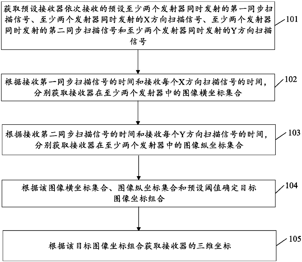
[0028] Such as figure 1 As shown, the embodiment of the present invention provides a real-time positioning method, including:

[0029] Step 101: Obtain the first synchronous scanning signal transmitted by at least two transmitters simultaneously, the X-direction scanning signal transmitted by at least two transmitters simultaneously, and the second synchronous scanning signal transmitted by at least two transmitters simultaneously, which are sequentially received by the preset receiver. The synchronous scanning signal and the Y-direction scanning signal simultaneously transmitted by at least two emitters.

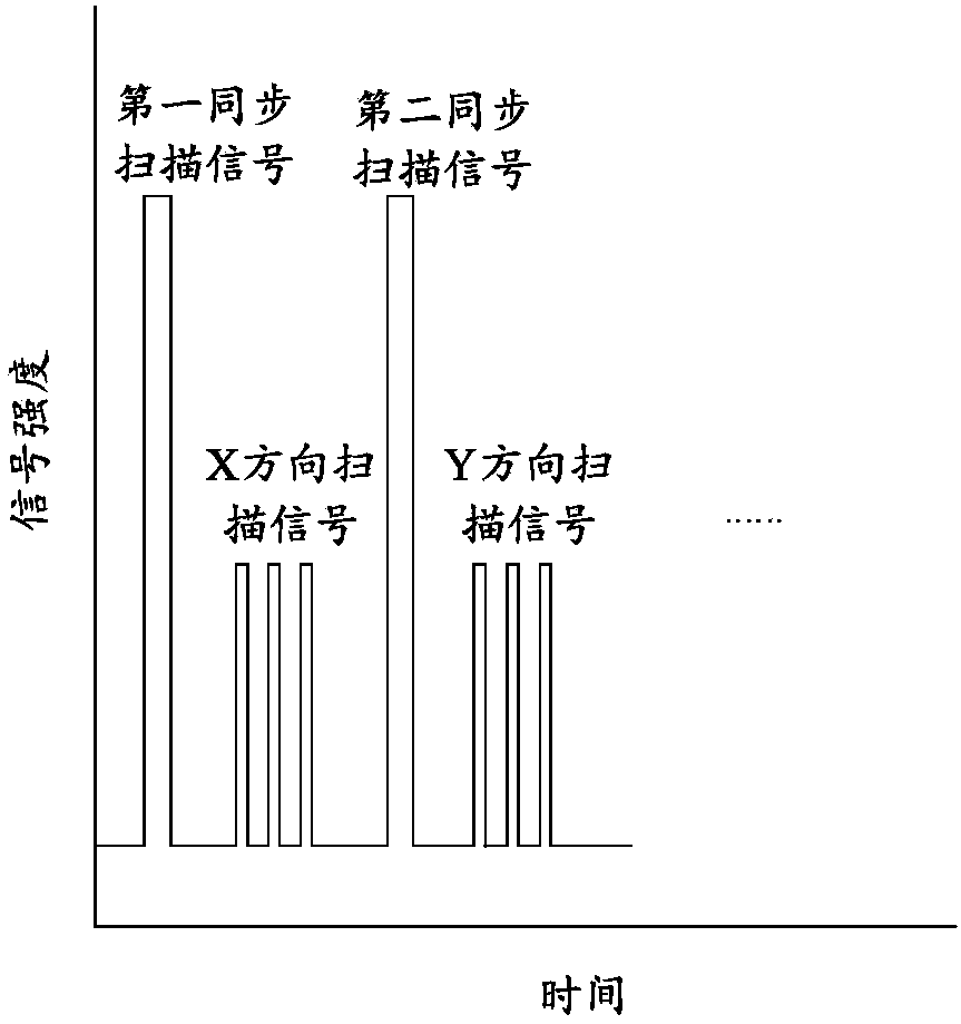
[0030] In this embodiment, the first synchronous scanning signal, the X-direction scanning signal, the second synchronous scanning signal and the Y-direction scanning signal can all be received by the receiver, and the signal waveform diagram of the receiver can be as follows figure 2 shown. Specifically, when real-time positioning is required, at first the built-in infr...

Embodiment 2

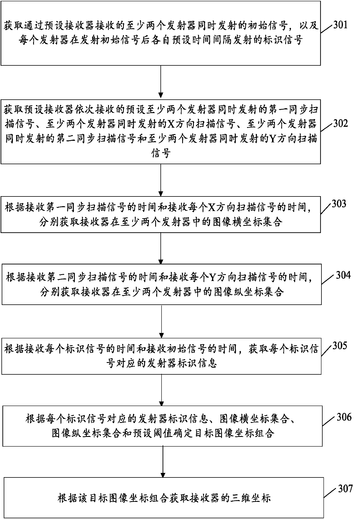
[0047] Such as image 3 As shown, the embodiment of the present invention provides a real-time positioning method, including:

[0048] Step 301, acquire initial signals transmitted simultaneously by at least two transmitters received by a preset receiver, and identification signals transmitted by each transmitter at a preset time interval after transmitting the initial signal.

[0049] In this embodiment, for the convenience of identifying the transmitters, the time intervals between the identification signal and the initial signal are different for each transmitter. In particular, an initial time interval Δt may be preset, and the identifier of each transmitter is multiplied by the initial time interval Δt as the time interval of each transmitter.

[0050] Step 302, acquiring the first synchronous scanning signal, the X-direction scanning signal, the second synchronous scanning signal and the Y-direction scanning signal. The process is related to figure 1 The shown step 10...

Embodiment 3

[0063] Such as Figure 5 As shown, the embodiment of the present invention provides a real-time positioning device, including:

[0064] The signal acquisition unit 501 is configured to acquire the first synchronous scanning signal simultaneously transmitted by at least two transmitters, the X-direction scanning signal simultaneously transmitted by the at least two transmitters, the at least two The second synchronous scanning signal transmitted by two transmitters and the Y-direction scanning signal transmitted by the at least two transmitters simultaneously;

[0065] The abscissa acquisition unit 502 is connected to the signal acquisition unit, and is used to acquire the receiver in the at least two The image abscissa collection in the launcher;

[0066] The ordinate acquisition unit 503 is connected to the signal acquisition unit, and is used to acquire the receiver in the at least two The collection of image ordinates in the emitter;

[0067] An image coordinate acquisi...


PUM


Abstract

The invention discloses a real-time positioning method and device, relates to the field of positioning, and aims at solving the problem that data refreshing rates cannot be ensured while tracking areas are expanded in the prior art. The method comprises the following steps of: S10, obtaining a first synchronous scanning signal, an X-direction scanning signal, a second synchronous scanning signal and a Y-direction scanning signal; S20, respectively obtaining image horizontal coordinate sets, in at least two emitters, of a receiver; S30, respectively obtaining image vertical coordinate sets, inthe at least two emitters, of the receiver; S40, determining a target image coordinate combination according to the image horizontal coordinate sets, the image vertical coordinate sets and a preset threshold value; and S50, obtaining a three-dimensional coordinate of the receiver according to the target image coordinate combination. The method and device can be used in the field of motion capture,surgical navigation and virtual reality needing accurate tracking and positioning.

Description

technical field [0001] The present disclosure generally relates to the field of positioning, and in particular, to a real-time positioning method and device. Background technique [0002] At present, precise tracking and positioning of users is required in fields such as motion capture, surgical navigation, and virtual reality. Taking Virtual Reality (VR) as an example, in a virtual reality environment, users need to be positioned in real time to adapt to what they see through virtual glasses, virtual helmets, etc., or to prevent users from bumping into other users or objects. [0003] In the prior art, the specific process of general real-time positioning includes: firstly transmit a frame synchronous scanning signal through the transmitter, then scan in the X direction and Y direction in turn, and determine the three-dimensional coordinates by collecting the laser scanning signal. When multiple transmitters are used in cascade, in order to avoid signal interference, the c...

Claims


Application Information

Patent Timeline
IPC IPC(8): G06T7/70G06T7/292
Inventor 李冬
Owner BEIJING SWEET TECH CO LTD
Why Eureka
Try Eureka