Photo frame module

A photo frame and frame technology, applied in the imaging field, can solve problems such as power consumption and non-environmental protection

Inactive Publication Date: 2018-01-19
PRIMAX ELECTRONICS LTD
View PDF4 Cites 0 Cited by
  • Summary
  • Abstract
  • Description
  • Claims
  • Application Information

AI Technical Summary

Problems solved by technology

[0004] However, the existing electronic photo frame 1 needs to be continuously powered to enable the image files to be continuously displayed on the display screen

Method used


Image

  • Photo frame module
  • Photo frame module
  • Photo frame module

Examples


Embodiment Construction

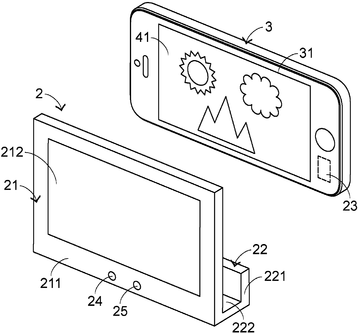
[0030] see image 3 , which is a schematic diagram of the appearance structure of a preferred embodiment of the photo frame module of the present invention. The photo frame module 2 includes a display device 21 and a fixing structure 22, and the fixing structure 22 is used to fix a terminal device 3 so that the screen 31 of the terminal device 3 is parallel to the display device 21; in this preferred embodiment, the fixing structure 22 includes a seat body 221, and the display device 21 is connected to the base body 221; wherein, the display device 21 and the base body 221 are in an inverted ㄇ shape, so an accommodating space 222 is formed between the display device 21 and the base body 221, so that the terminal The device 3 is placed and fixed in the accommodating space 222 . In addition, the terminal device 3 can be a portable electronic device, such as a mobile phone, a tablet computer, etc., but is not limited thereto.

[0031] see Figure 4 , which is image 3 The thr...


PUM


Abstract

The invention provides a photo frame module. The photo frame module comprises a display device and a fixing structure, wherein the display device comprises a plurality of sensing units, the fixing structure is used for fixing a terminal device so that a screen of the terminal device is parallel to the display device, and the sensing units are used for sensing an original image shown on the screenof the terminal device after the terminal device is fixed, so that a sensed image corresponding to the original image is shown on the display device.

Description

technical field [0001] The invention relates to the field of images, in particular to a photo frame module for displaying images. Background technique [0002] With the development of technology, the electronic display device has become a very common electronic consumer product. Its main function is to provide the output of image files, and the image files include static photo electronic files and dynamic video electronic files. Generally speaking, electronic display devices include televisions, computer screens, electronic photo frames, and electronic signage, etc. In the era of photo digitization, the demand for electronic photo frames has increased significantly. [0003] Next, a conventional electronic photo frame will be described. see figure 1 and figure 2 , figure 1 It is a schematic diagram of the appearance structure of an existing electronic photo frame, figure 2 for figure 1 A schematic diagram of the appearance structure of the electronic photo frame show...

Claims


Application Information

Patent Timeline
IPC IPC(8): G09F9/00
Inventor 林育民
Owner PRIMAX ELECTRONICS LTD
Why Eureka
Try Eureka